7B.1 Introduction
Fixation devices control the movement at a fracture. This chapter covers:
- The basic theory that applies to all fixation.
- Craniofacial fixation in detail, because this is where plastic surgeons use plates most.
- Fixation in the hand.
- A short account of nails and external fixators, which are applied by orthopedic surgeons but which we must understand when we plan flap cover.
The four AO principles apply to every region: (1) reduction, (2) stable fixation, (3) preservation of blood supply, (4) early mobilization. In the face there is a fifth requirement: restoration of the occlusion.
Flowchart: Overview of fixation
- Fixation
- General principles
- Biomechanics
- Absolute, relative and functional stability
- Screwslag, position, locking
- Plates by function
- Craniofacial fixation
- Implants and MMF
- Mandible
- Load-sharingminiplates
- Load-bearingreconstruction plate
- Midface
- Buttresses
- Orbit
- Osteotomies, flaps, grafts
- Children
- Hand
- K-wires, lag screws, plates
- Orthopedic devices
- Nail
- External fixator
- General principles
7B.2 Basic biomechanics
| Term | Meaning | Why it matters |
|---|---|---|
| Load | Force on bone or implant: tension, compression, bending, torsion, shear | Bone is strongest in compression, weakest in shear |
| Stress | Force per unit area | A thin plate has high stress for the same load |
| Strain | Change in length ÷ original length | Decides the tissue that forms in a fracture gap |
| Stiffness | Resistance to deformation | Decides how much the fracture moves under load |
| Strength | Load at which the construct fails | Different from stiffness: a construct can be stiff but break early |
| Young's modulus | Stiffness of the material itself | Cortical bone 15 to 20 GPa; titanium about 110 GPa; stainless steel about 200 GPa |
| Fatigue failure | Failure after many load cycles below breaking strength | If the bone does not unite, every plate eventually breaks |
| Load-sharing | Bone and implant both carry load | Small plates are enough |
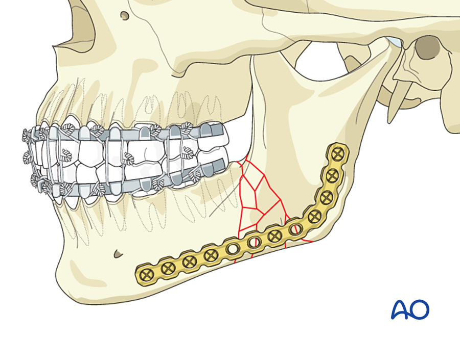
| Load-bearing | The implant carries all the load | Needs a large, strong plate |
The bending stiffness of a plate is proportional to its width × thickness3. Doubling the thickness makes it 8 times stiffer. This is why a 2.5 mm reconstruction plate behaves so differently from a 1 mm miniplate.
Implant materials. Almost all craniofacial implants are titanium: its modulus is closer to bone than steel, it is biocompatible, it osseointegrates, and it causes less artifact on CT and MRI. Resorbable plates (PLLA, PGA copolymers) are used in infants and young children.
7B.3 Absolute and relative stability
| Absolute stability | Relative stability | |
|---|---|---|
| Definition | No movement at the fracture under functional load | Small controlled movement |
| Achieved by | Compression between fragments (friction) | Splinting |
| Healing | Primary, no callus | Secondary, with callus |
| Needs | Anatomical reduction; simple fracture | Alignment; suits comminution |
| Devices | Lag screw, compression plate, tension band | K-wires, bridging (reconstruction) plate, external fixator, intermaxillary fixation, nail |
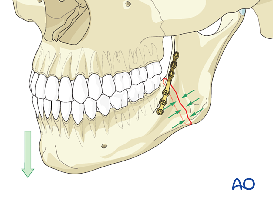
In craniofacial surgery a third term is used: functionally stable fixation. A miniplate on the mandible does not abolish all movement, but it is stable enough to allow function (mouth opening, soft diet) while the bone heals. This is the basis of the Champy technique.
7B.4 Screws
7B.4.1 Parts of a screw
- Core diameter: decides screw strength. The drill for a threaded (pilot) hole equals the core diameter.
- Thread (outer) diameter: decides holding power. Screws are named by this (1.5, 2.0, 2.4 mm). The drill for a gliding hole equals the thread diameter.
- Self-tapping screws cut their own thread. Self-drilling screws need no pilot hole; they are used in thin midface bone and as IMF screws.
- Emergency screw: slightly larger diameter, used when a hole has been stripped.
- Monocortical screws (4 to 8 mm) are used where tooth roots or the inferior alveolar nerve are at risk. Bicortical screws hold better and are used at the lower border of the mandible.
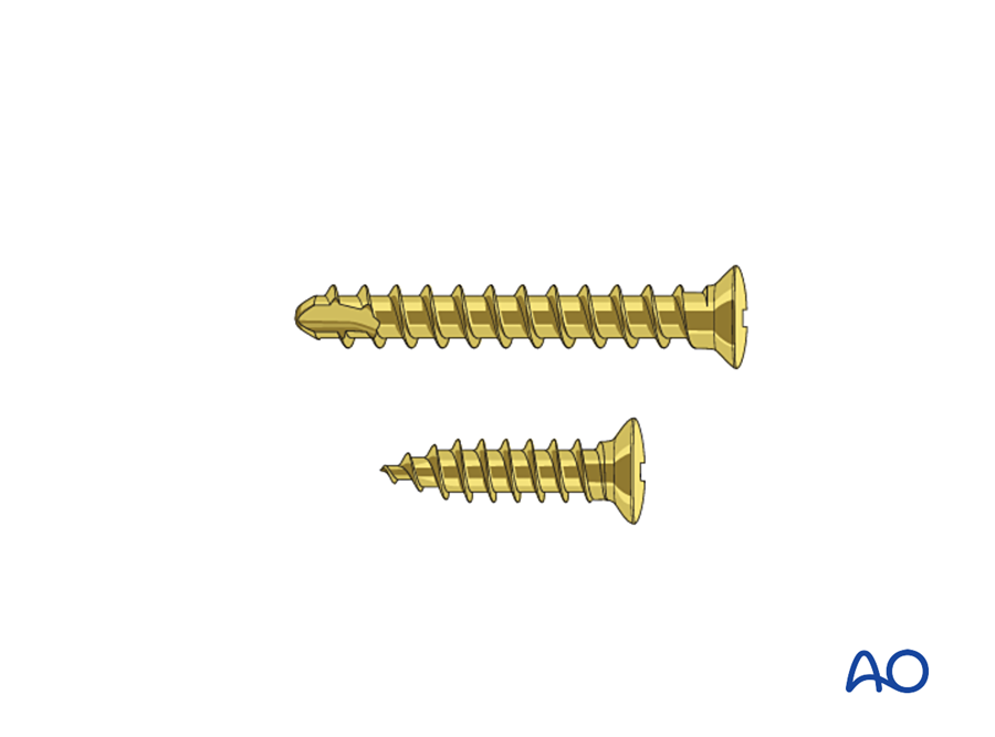
7B.4.2 The lag screw
A lag screw compresses two fragments. It gives absolute stability with very little hardware. The thread must grip only the far fragment.
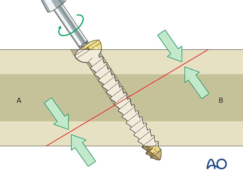
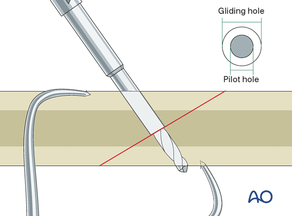
Steps: (1) reduce and hold; (2) drill the gliding hole in the near fragment; (3) drill the pilot hole in the far fragment through a drill sleeve; (4) countersink; (5) measure and insert the screw.
- Direction: perpendicular to the fracture plane.
- One lag screw does not control rotation: use two, or one screw with a plate.
- Not for comminuted fractures or defects: compression collapses them.
- Our uses: oblique fractures of the symphysis and mandibular body, condylar head fractures, oblique phalangeal and metacarpal fractures, fixation of onlay bone grafts.
7B.4.3 Position screw
Both cortices are threaded, so the fragments are held at a fixed distance without compression. Used in the sagittal split osteotomy, where compression would crush the inferior alveolar nerve and rotate the condyle.
7B.5 Plates: general principles
A plate is named by the function it performs. The functions below were developed for long bones. They are listed briefly, with the craniofacial equivalent of each.
| Function | How it works | Stability | Craniofacial equivalent |
|---|---|---|---|
| Compression plate | Oval holes with a slope: an eccentrically placed screw slides down the slope and pushes the fragment toward the fracture (dynamic compression plate, DCP) | Absolute | Compression plates were used at the lower border of the mandible (Luhr, Spiessl). Now largely replaced by miniplates. |
| Protection (neutralization) plate | Protects a lag screw from bending and torsion | Absolute | Lag screw plus miniplate in an oblique mandibular fracture |
| Buttress plate | Supports a fragment against shear or collapse | Absolute | Plates on the facial buttresses |
| Tension band plate | Placed on the tension side; converts load into compression at the opposite cortex | Functionally stable | The Champy miniplate |
| Bridge plate | Spans a comminuted zone or defect; fixed only in sound bone at each end | Relative; load-bearing | The reconstruction plate |

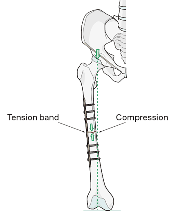
Long-bone plating developed from the DCP (1969) to the limited-contact DCP and then to locking plates, mainly to reduce damage to the periosteal blood supply under the plate. Details of long-bone plating are outside the scope of this chapter.
7B.5.1 Locking plates
In a conventional plate the screws pull the plate onto the bone, and stability comes from friction. The plate must be bent to fit exactly. If it does not fit, tightening the screws pulls the bone to the plate and the reduction (and the occlusion) is lost.
In a locking plate the screw head is threaded and locks into the plate. Plate and screws form one fixed-angle unit, like an external fixator under the skin.
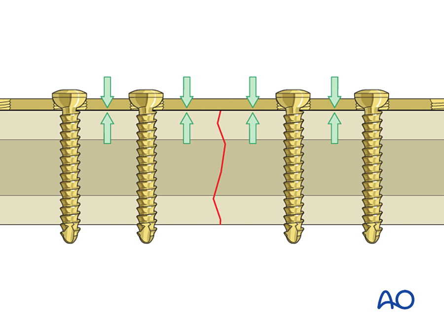
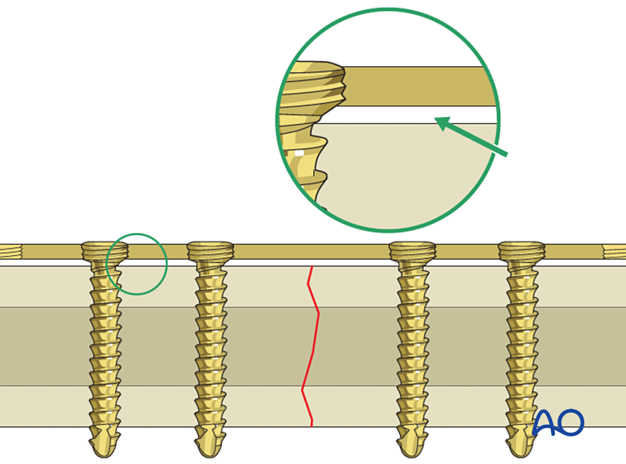
| Conventional | Locking | |
|---|---|---|
| Stability from | Friction between plate and bone | Fixed angle between screw and plate |
| Plate contouring | Must be exact | Less critical |
| Periosteal blood supply | Compressed under the plate | Preserved |
| Screw loosening | One loose screw weakens the construct | Screws cannot back out of the plate; all must fail together |
| Poor bone (atrophic, irradiated) | Poor hold | Better hold |
Use: locking reconstruction plates for mandibular defects and free flap reconstruction; comminuted and atrophic mandibular fractures. A locking plate does not reduce the fracture: reduce first, then lock. (Egol 2004; Wagner 2003)
7B.6 Craniofacial fixation
Flowchart: Steps in fixing a facial fracture
- CT and plan
- Airway and exposure
- Set the occlusionMMF
- Reduce
- Fix: stable bone → unstable bone
- Check occlusionrelease MMF
- Soft tissue closure
7B.6.1 Principles of craniofacial plating
Before the fixation of each region is described, this section sets out the principles that apply to every plate placed on the facial skeleton.
Flowchart: The principles of craniofacial plating
- 1. Reduce accurately
- 2. Match the fixation to the load
- 3. Place the plate where it works
- 4. Enough screws, correctly placed
- 5. Adapt the plate passively
- 6. Preserve blood supply
- 7. Stable bone to unstable bone
- 8. Replace missing bone
- 9. Repair the soft tissue
- 10. Early function
Aims. The aims of fixing the facial skeleton are to restore form (facial width, projection and height) and function (occlusion and chewing, eye position and movement, the nasal airway), and to let the patient use the jaw immediately, without prolonged wiring of the teeth.
How the principles developed. Three schools of treatment came one after another. The present approach combines them.
| Period and school | Method | Type of stability | Limitation |
|---|---|---|---|
| Before the 1970s: wire osteosynthesis | Interosseous wires across the fracture, plus MMF for 4 to 6 weeks | Not stable: the wire only holds the fragments together | Weeks of MMF; malunion; infection; airway and nutrition problems |
| Late 1960s to 1970s: rigid compression plating (Luhr; Spiessl and the AO group) | Thick compression plate at the lower border of the mandible with bicortical screws, often with a tension band (arch bar or small plate) at the upper border | Absolute stability; primary bone healing | External (skin) approach with scar and facial nerve risk; large plates; small errors in plate bending change the occlusion; compression can open the lingual cortex |
| 1973 to 1978: miniplate osteosynthesis (Michelet; Champy) | Small, bendable plate with monocortical screws on the tension line, placed through the mouth | Functionally stable; load-sharing | Not strong enough when the bone cannot share the load (comminution, defect, atrophy, infection) |
| Today | Choose along a range: miniplates for load-sharing situations; locking reconstruction plates for load-bearing situations; 3D planning and patient-specific plates for complex cases | Matched to the fracture | Needs a correct assessment of the fracture and the bone |
Principle 1. Reduction comes first, and the occlusion is the key.
- A plate only holds the position it is given. It cannot correct a poor reduction.
- In any fracture of a tooth-bearing bone, the teeth are placed in occlusion and held with MMF before any plate is applied.
- Where there are no teeth to guide, the reduction is judged from fixed bony landmarks: the buttresses, the orbital rims, the piriform rim, and the sphenozygomatic suture in the lateral orbital wall.
- The exposure must be wide enough to see these landmarks, and no wider.
- After plating, the MMF is released and the occlusion is checked again with the condyles seated in their fossae.
Principle 2. Match the strength of the fixation to the load.
- The upper face (frontal bone, naso-orbito-ethmoid region) carries almost no load: microplates are enough.
- The midface carries a moderate load along its buttresses: miniplates on the buttresses.
- The mandible carries the full force of chewing. Here the decision is whether the bone can share the load. If it can, miniplates are enough. If it cannot, the plate must be strong enough to carry all the load.
- Bite force is much reduced for several weeks after a fracture. This is one reason why small plates are adequate in practice for simple fractures.
- Using a larger plate than necessary has costs: more dissection, a more palpable plate, and more stress shielding.
Principle 3. Place the plate where it works best.
- On the tension side. A plate resists being pulled apart much better than it resists bending. In the mandible the tension side is the upper border, so plates follow Champy's ideal lines.
- Along the buttresses in the midface, where the bone is thick enough to hold screws and where the load passes.
- In thick bone, away from tooth roots, tooth buds and nerve canals.
- At right angles across the fracture line, with the fracture under the middle of the plate. No screw is placed in the fracture line.
- Where there is torsion (the symphysis), one plate is not enough: two plates, or two lag screws.
Principle 4. Use enough screws, and place them correctly.
- At least two screws on each side of the fracture for a miniplate. One screw allows the fragment to rotate around it.
- At least three (preferably four) screws on each side for a load-bearing reconstruction plate.
- Monocortical screws where roots or the nerve canal lie beneath the plate. Bicortical screws at the lower border of the mandible and for reconstruction plates.
- Drilling: sharp drill, low speed, continuous irrigation. Heat kills bone around the hole, and the screw then loosens.
- The drill is held steady and perpendicular. A wobbling drill makes an oval hole with poor hold.
- Screws are tightened by hand until firm. Over-tightening strips the thread, especially in thin midface bone. A stripped hole is rescued with an emergency screw or by using another plate hole.
- With non-locking plates the screw is placed in the center of the plate hole. Placing it eccentrically moves the fragment and can change the occlusion.
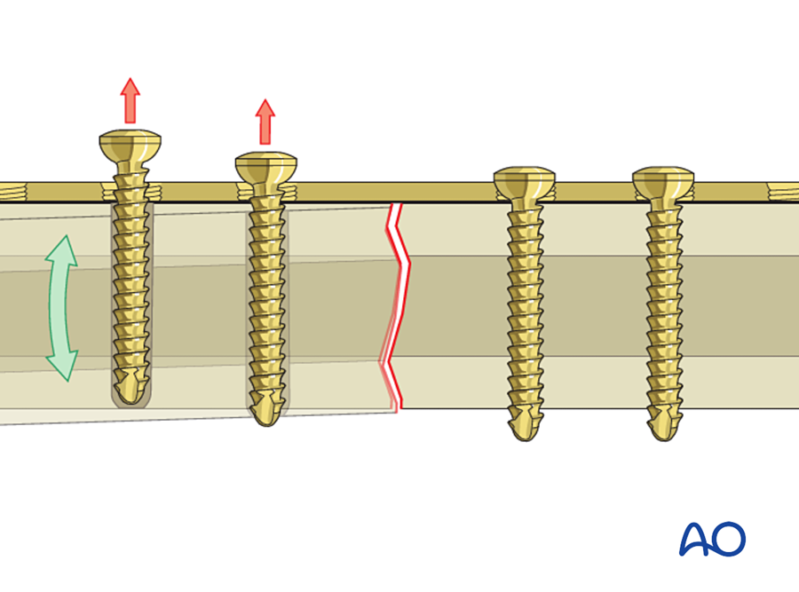
Principle 5. Adapt the plate passively to the bone.
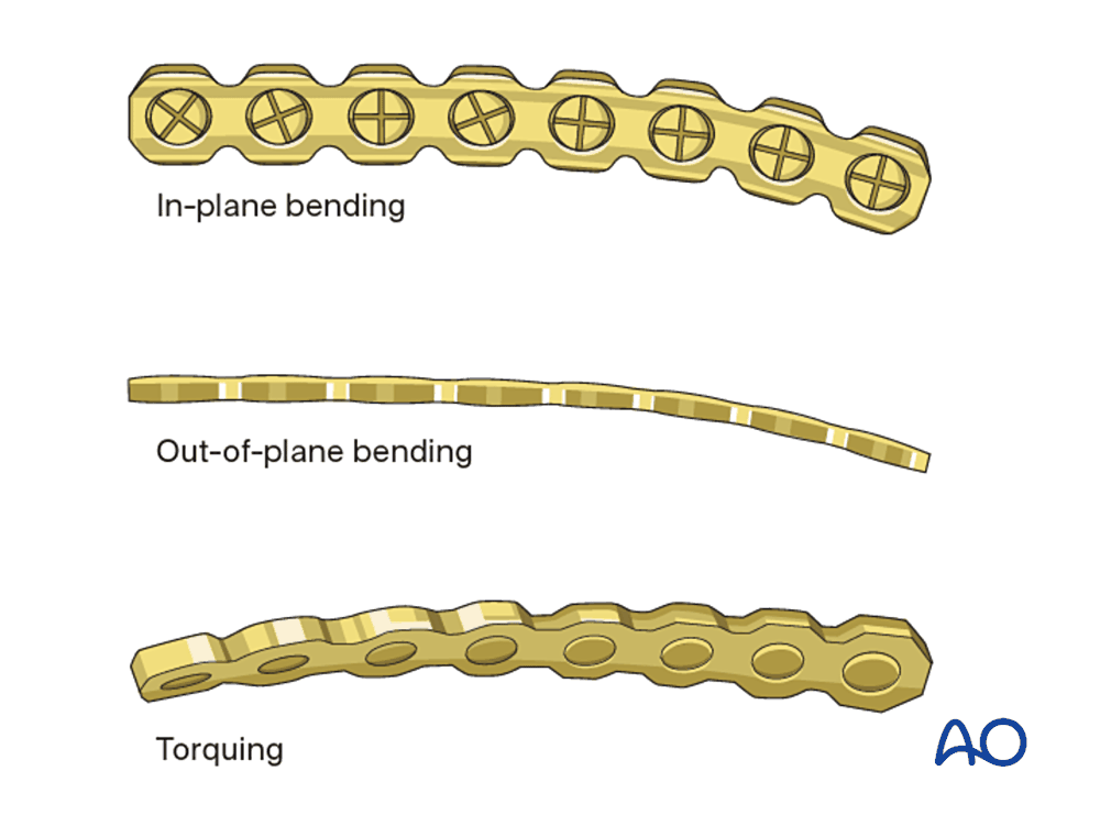
- The plate must lie on the bone without force along its whole length. A bending template can be shaped on the bone first and the plate bent to match it.
- With a non-locking plate, any gap between plate and bone is closed by the screws, which pull the bone to the plate. The fragments move, and the occlusion or the condylar position changes.
- With a locking plate, small errors of fit are tolerated because the screws lock to the plate without pulling the bone.
- In the mandible the plate is slightly over-bent, so that the far (lingual) cortex closes when the screws are tightened. An under-bent plate opens the lingual cortex and widens the mandible.
- Each bend weakens the plate. Bending back and forth can cause the plate to break later.
Principle 6. Preserve the blood supply.
- The periosteum is lifted only as far as is needed to see the fracture and seat the plate.
- Small fragments are left attached to their periosteum and soft tissue wherever possible.
- Approaches through the mouth and through existing lacerations disturb the blood supply least.
- This matters most in the atrophic mandible and in irradiated bone, where the periosteum is the main blood supply.
Principle 7. Work from stable bone to unstable bone.
- Each fragment is fixed to a part that is already in the correct position: the skull above, or the reconstructed mandible below.
- A comminuted fracture is first "simplified": small fragments are joined to each other with miniplates until there are only two main segments, which are then fixed with the definitive plate.
- The three dimensions are restored in order: width first, then projection, then height. Errors in width (a wide face) are the most common and the hardest to correct later.
Principle 8. Replace missing bone at the first operation.
- A gap in a buttress of more than about 5 mm is bridged with a bone graft, fixed under or beside the plate.
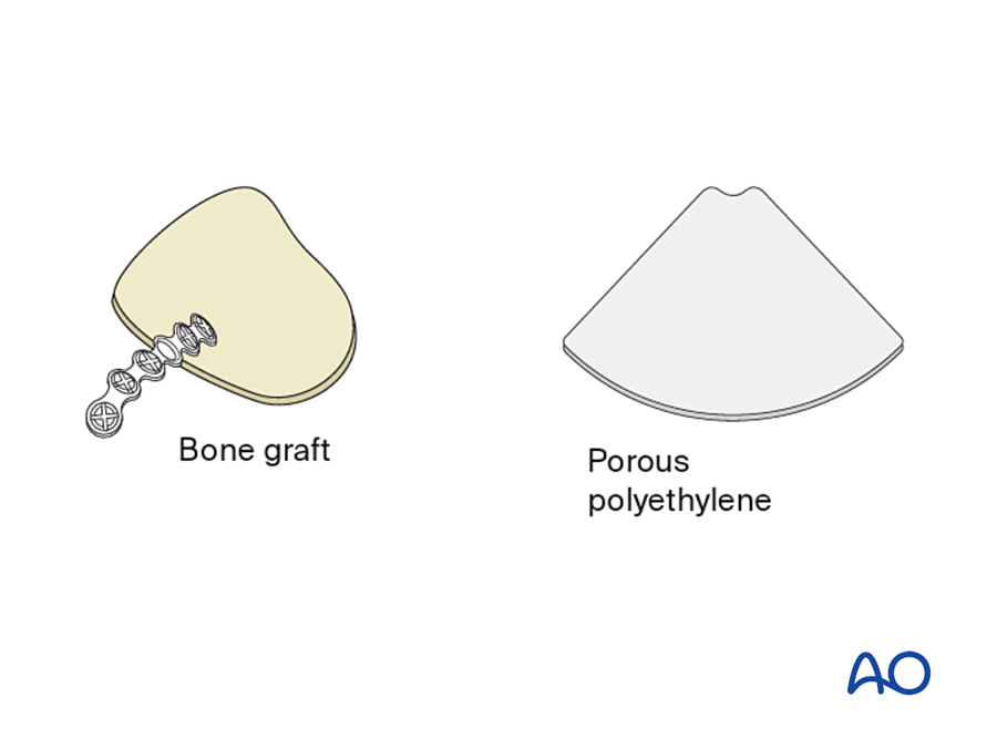
- Defects of the orbital walls are covered with a thin sheet (titanium mesh, polyethylene or bone) to restore orbital volume.
- If bone is not replaced early, the soft tissue contracts into the gap and the deformity becomes very difficult to correct later.
- A segmental defect of the mandible is spanned with a reconstruction plate to hold the segments in position until bone is brought in.
Principle 9. Repair and resuspend the soft tissue.
- When the periosteum is lifted off the midface or chin, the soft tissue drops. The periosteum and muscles (cheek soft tissue, mentalis, the canthi) are resuspended to bone at closure.
- Mucosa over a plate is closed watertight and without tension.
- A plate must be covered by healthy soft tissue. In a contaminated or irradiated bed, or with tissue loss, a flap is planned at the same time as the plate.
Principle 10. Allow early function, and check the result.
- With stable fixation the MMF is released at the end of the operation. The patient takes a soft diet for about 4 to 6 weeks. Guiding elastics are used if the occlusion needs fine adjustment.
- Postoperative imaging (CT for the midface and orbit) confirms the reduction and the position of the implants.
- Timing: fixation is easiest and most accurate within the first 1 to 2 weeks, before the fragments become fixed by callus and the soft tissue scars. Fractures open to the mouth are given antibiotics around the operation.
Summary: type of fixation by region
| Region | Load | Plate | Screws | Type of stability |
|---|---|---|---|---|
| Frontal bone, naso-orbito-ethmoid, orbital rims | Very low | Microplates 1.0 to 1.3 mm; mesh | Monocortical, 3 to 5 mm | Holds position |
| Midface buttresses, zygoma | Moderate | Miniplates 1.5 to 2.0 mm | Monocortical, 4 to 6 mm | Buttress reconstruction |
| Orbital walls | None | Mesh, preformed plate, sheet | One or two at the rim | Contour and volume only |
| Mandible, simple fracture | High, shared with bone | Miniplates 2.0 mm on the tension line | Monocortical above, bicortical at the lower border | Functionally stable (load-sharing) |
| Mandible: comminuted, atrophic, infected, defect | High, carried by the plate | Locking reconstruction plate 2.4 mm or larger | Bicortical, 3 to 4 each side | Load-bearing |
7B.6.2 Practical decisions: when to plate, reference points, and where to start
The principles above become three practical questions for every facial fracture:
- When do I operate?
- What do I use as my reference point?
- Where do I start?
This section answers them, first in general and then fracture by fracture. Each fracture is set out in the same order: when to plate, when not to plate, reference points, order of work, approach, and the check before closing.
A. General answers for all facial fractures
When do I plate?
- When the fracture is displaced or unstable, and
- it causes, or will cause, a functional problem: malocclusion, restricted mouth opening, diplopia or muscle entrapment, enophthalmos, airway or nasal obstruction, CSF leak; or
- it causes a visible deformity: flat cheek, wide or long face, telecanthus, contour defect.
When do I not plate?
- Undisplaced, stable fracture with normal occlusion and no functional deficit.
- Treatment: soft diet, analgesia, and review with repeat examination.
When is it an emergency?
- Airway obstruction.
- Uncontrolled bleeding.
- Retrobulbar hematoma or optic nerve compression.
- Trapped extraocular muscle in a child ("white-eyed" blow-out), often with nausea and a slow pulse.
Timing of all other fractures
- Either early, before swelling develops, or after it settles (about 5 to 10 days).
- Aim to operate within about 2 weeks in adults and about 1 week in children, before the fragments are fixed by callus.
- A delay of a few days for a mandibular fracture has not been shown to increase infection or nonunion, provided antibiotics are given (Hermund 2008).
What is my reference point? In order of reliability:
- The occlusion.
- Intact bone next to the fracture: the skull above, an uninjured buttress, the opposite side.
- Fixed anatomical landmarks: sphenozygomatic suture, orbital rims, piriform rim, posterior ledge of the orbital floor, intercanthal distance.
Where do I start?
- Start from what is stable and certain and work toward what is unstable.
- Set the occlusion first.
- Fix first the fragment that can be reduced exactly.
- Restore width, then projection, then height.
What do I need before surgery?
- Fine-cut CT of the face with coronal, sagittal and 3D views.
- Eye examination: acuity, pupils, movements, diplopia.
- Occlusion and dental status.
- Cervical spine and head injury cleared.
- Photographs.
B. Mandible
When do I plate?
- Displaced or mobile fracture.
- Malocclusion.
- More than one fracture.
- Fracture combined with a midface fracture (the mandible is needed as a base).
- Comminuted, infected or atrophic edentulous fracture.
- Patient who cannot tolerate MMF: epilepsy, psychiatric illness, alcohol dependence, poor lung function.
When is it treated without plating?
- Undisplaced, favorable fracture with a full dentition and normal occlusion: MMF for 4 to 6 weeks, or soft diet with close review.
- Most fractures in young children.
- Coronoid fractures.
- Many condylar fractures.
Favorable and unfavorable fractures. A fracture line is "unfavorable" when the pull of the muscles (masseter, medial pterygoid and temporalis on the posterior fragment; the suprahyoid muscles on the anterior fragment) separates the fragments, and "favorable" when it pushes them together. Unfavorable fractures need fixation.
What are my reference points?
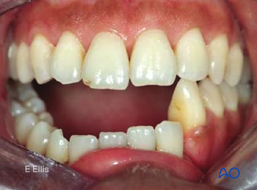
- The occlusion: wear facets, dental midlines, how the cusps fit. Ask the patient whether the bite feels normal.
- Alignment of the lower border.
- Alignment of the lingual cortex.
- The condyles must be seated in their fossae.
Where do I start, and in what order?
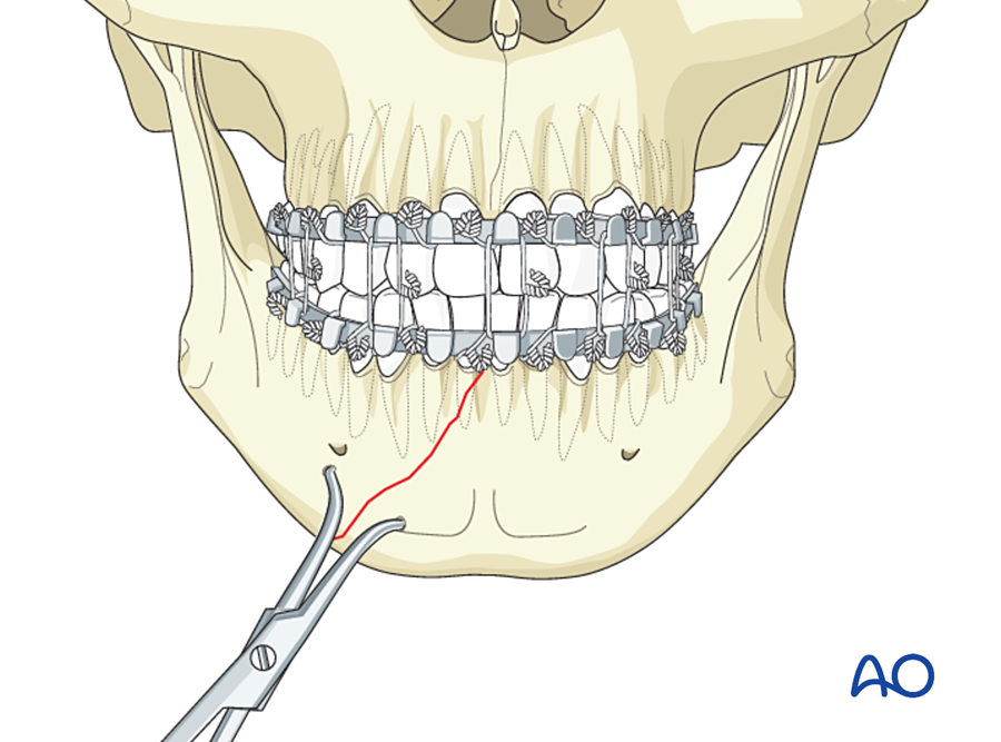
- Apply arch bars or IMF screws and place the teeth in occlusion (MMF).
- With several fractures, fix the tooth-bearing fractures first (symphysis, body), because the occlusion reduces them exactly. Then the angle. Then the condyle.
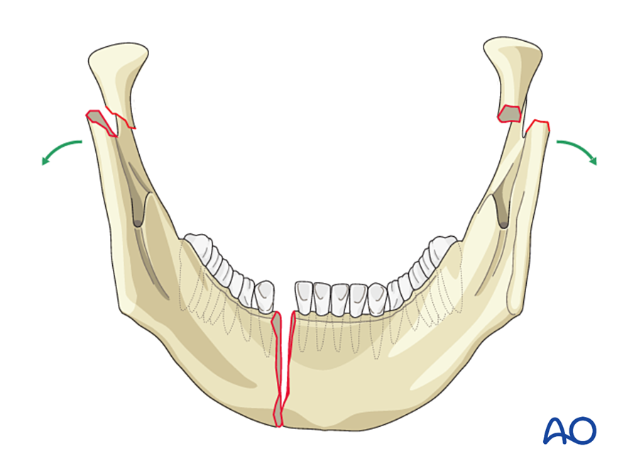
- In a symphysis fracture with condylar fractures, press the angles inward and over-bend the plate so that the lingual cortex closes. Otherwise the mandible, and the whole lower face, is left too wide.
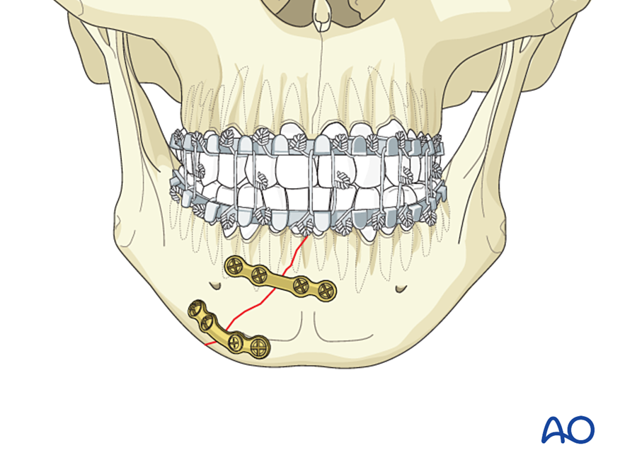
- At the symphysis the arch bar already holds the upper border, so the lower border plate is commonly placed first, then the upper plate.
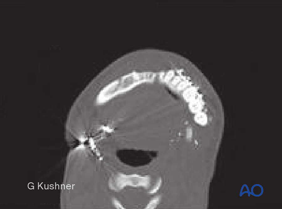
Approach
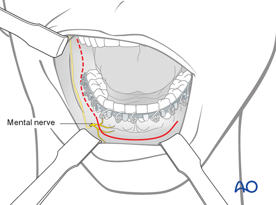
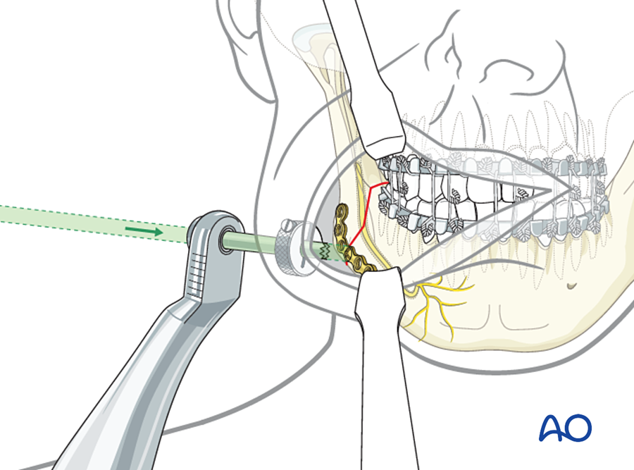
- Through the mouth (vestibular incision) for symphysis, body and angle. A transbuccal trocar is used for screws at the angle if needed.
- Through the skin (submandibular, retromandibular) for comminuted or atrophic fractures and for the condyle.
- Through an existing laceration when there is one.
How do I check before closing?
- Release the MMF.
- Open and close the jaw by hand with the condyles seated. The teeth must meet in the pre-injury occlusion without guidance.
- Check that the lower border is level and that there is no lingual gap.
C. Zygomaticomaxillary complex (ZMC)
When do I plate?
- Visible flattening of the cheek or facial asymmetry.
- Enophthalmos or a change in globe position.
- Diplopia with entrapment.
- Restricted mouth opening (the depressed arch blocks the coronoid process).
- Comminuted or high-energy fracture on CT.
When is it treated without plating?
- Undisplaced or minimally displaced fracture with no functional problem.
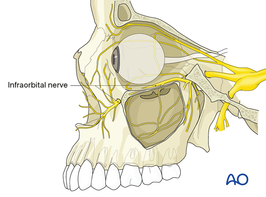
- Numbness in the infraorbital nerve area alone is not an indication.
The zygoma joins the rest of the skull at four places and also forms part of the orbit. One point is never enough to judge the reduction, because the bone can rotate around any single point.
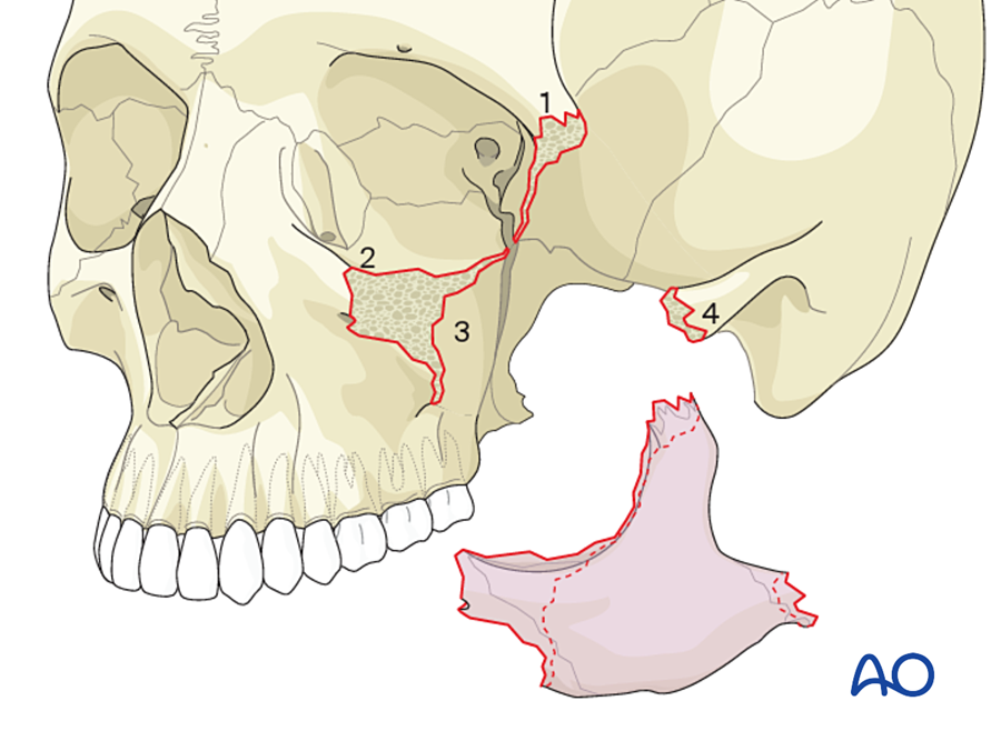
What are my reference points? In order of reliability:
- Sphenozygomatic suture (lateral orbital wall, seen from inside the orbit). The most reliable, because it shows rotation.
- Zygomaticomaxillary buttress.
- Infraorbital rim.
- Zygomaticofrontal suture. Strong bone for fixation, but a poor guide on its own, because the zygoma can rotate around it.
- Zygomatic arch. It sets projection and facial width in comminuted fractures.
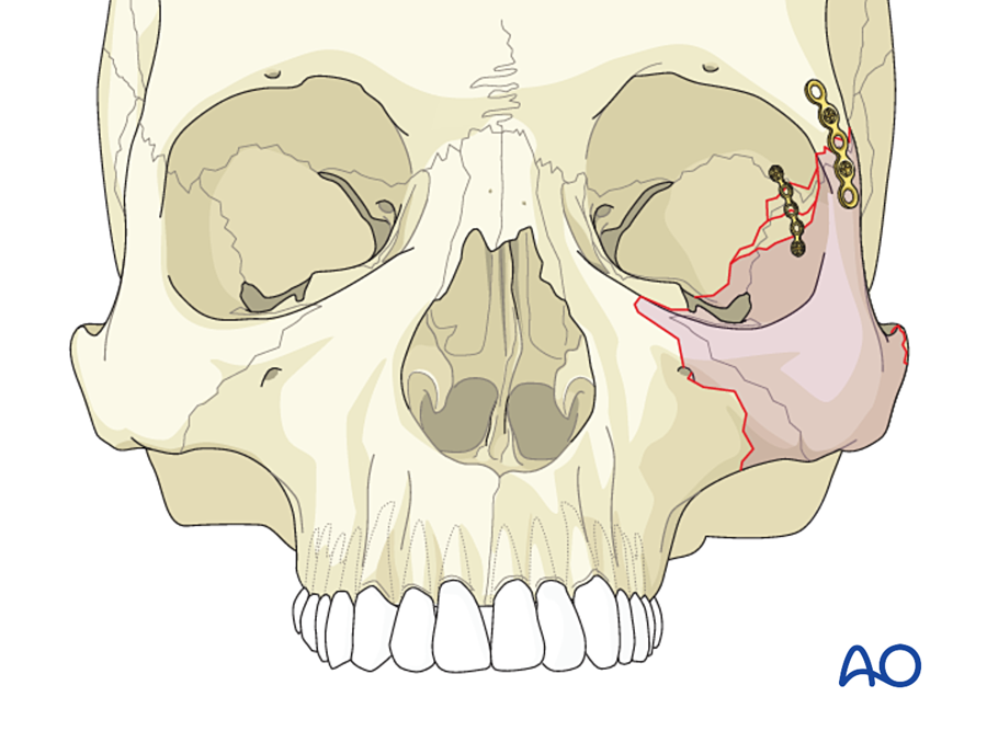
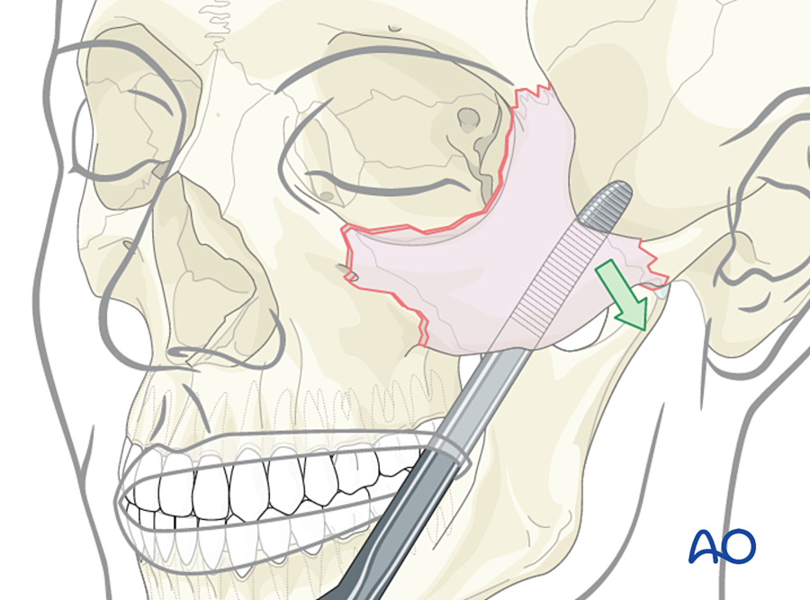
Where do I start, and in what order?
- Reduce: elevator through a temporal or intraoral approach, or a bone hook or threaded screw in the body of the zygoma.
- Check at least three points.
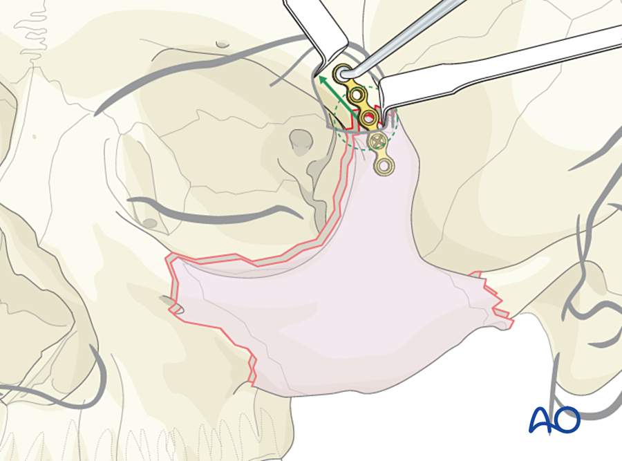
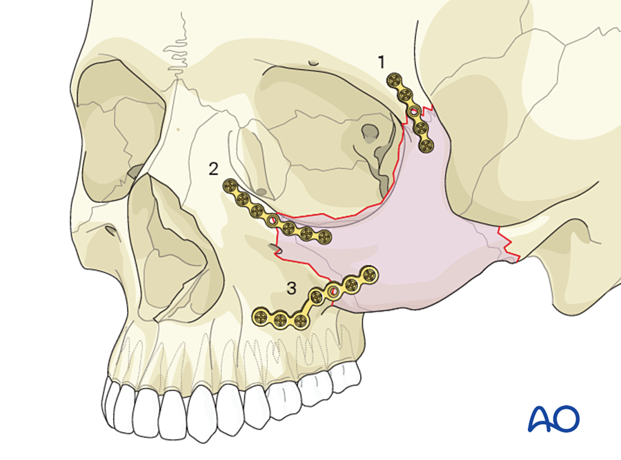
- First plate at the zygomaticofrontal suture (strongest bone). It can be left slightly loose while the other points are checked.
- Then the zygomaticomaxillary buttress (resists the downward pull of the masseter).
- Then the infraorbital rim, if needed (thin plate, because it can be felt through the skin).
- In comminuted fractures the arch is exposed through a coronal incision and reconstructed first, as a straight (not curved) arch, because it sets projection and width.
- Last, explore and reconstruct the orbital floor if indicated.
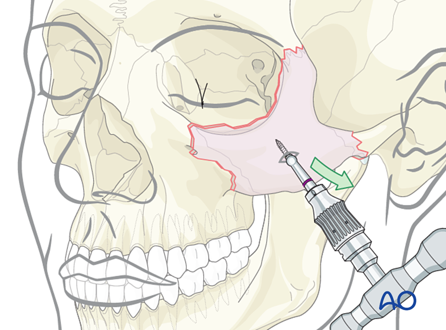
Approach
- Lateral brow or upper eyelid incision: zygomaticofrontal suture.
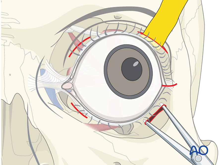
- Transconjunctival or lower eyelid incision: rim and floor.
- Upper buccal sulcus: buttress.
- Coronal: arch.
How do I check before closing?
- Cheek prominence and globe position compared with the other side, looking from above and from below.
- Forced duction test.
- Palpate the rims.
Number of fixation points: one for a simple fracture that is stable after reduction; two or three for most displaced fractures; four when the arch is comminuted (Ellis and Kittidumkerng 1996; Zingg 1992; Manson 1990).
D. Isolated zygomatic arch
When do I treat?
- Restricted mouth opening, or a visible depression.
- An undisplaced fracture is left alone.
What is my reference point?
- The contour of the arch by palpation, compared with the other side.
How is it done?
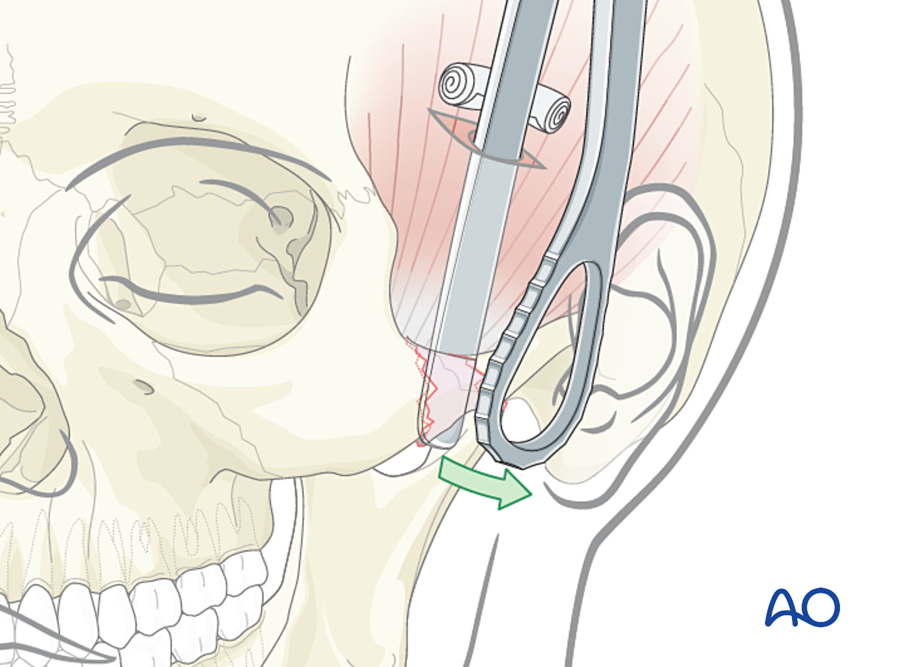
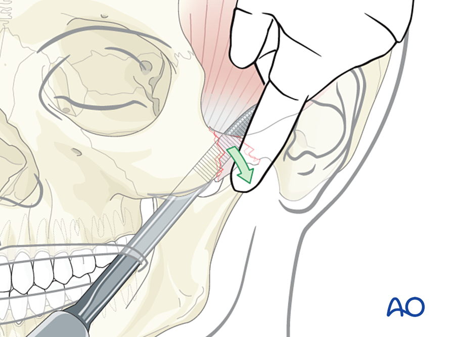
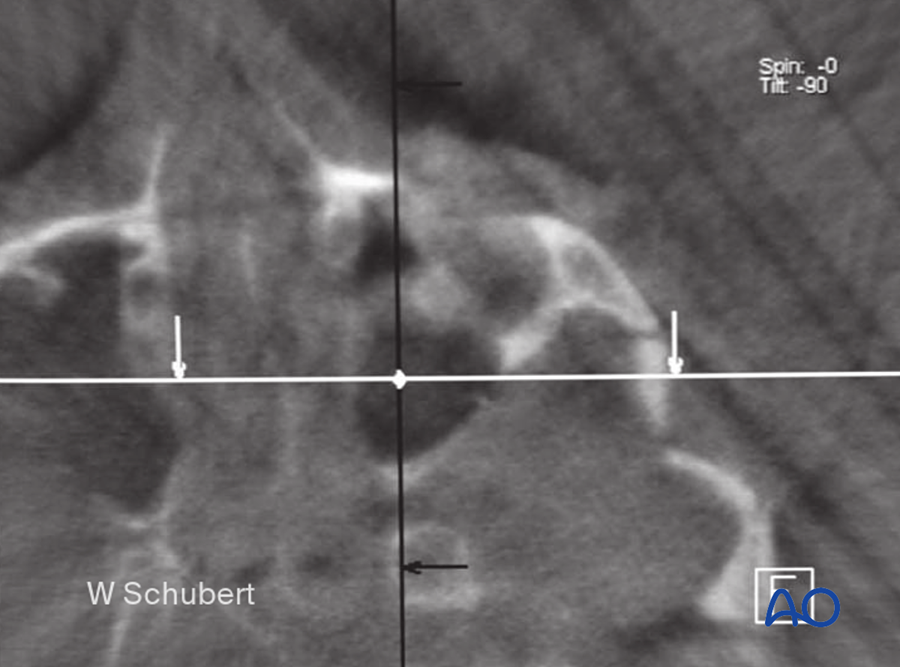
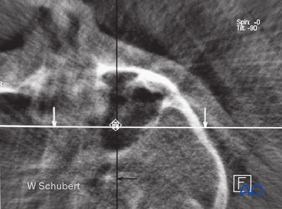
- Closed elevation through a temporal (Gillies) or intraoral (Keen) approach.
- In the Gillies approach the incision is in the temporal hairline. The elevator passes deep to the deep temporal fascia, on the surface of the temporalis muscle. This plane leads under the arch.
- The reduced arch is usually stable and is not plated.
- Protect it from pressure for 2 weeks.
How do I check before finishing?
- Mouth opening.
- Contour of the arch.
E. Orbital floor and medial wall (blow-out fracture)
When do I operate immediately (within 24 to 48 hours)?
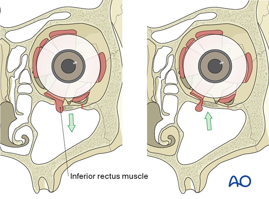
- Trapped muscle with restricted eye movement, especially in a child with a "white-eyed" blow-out.
- Nausea, vomiting and slow pulse (oculocardiac reflex).
When do I operate within 2 weeks?
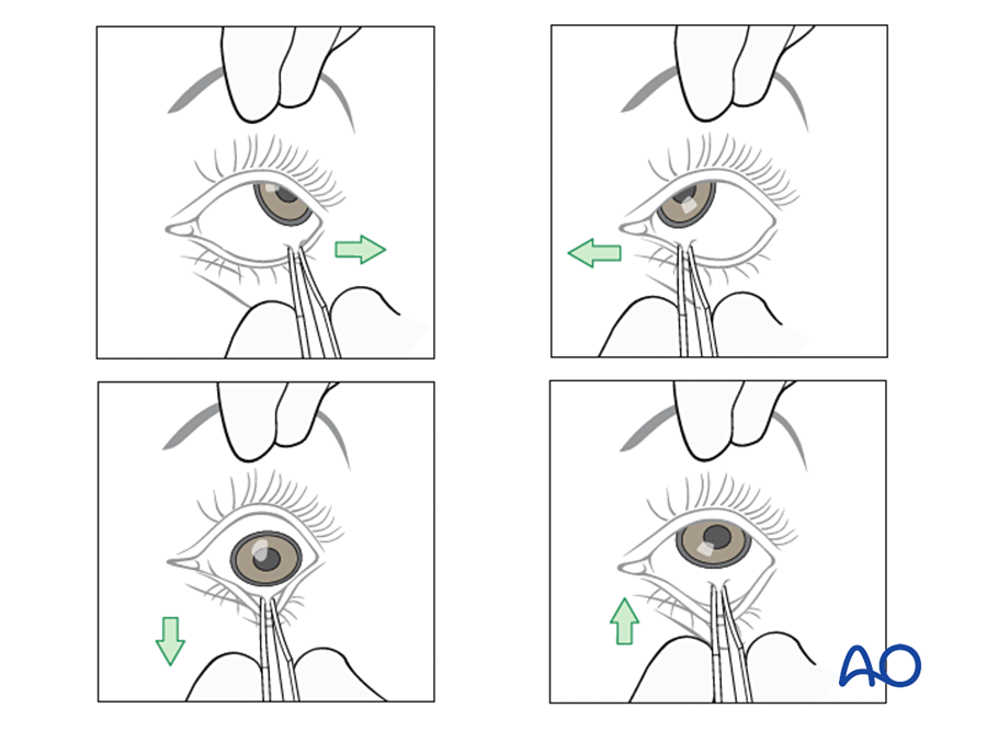
- Symptomatic diplopia that is not improving, with a positive forced duction test and entrapment on CT.
- Enophthalmos of more than 2 mm.
- A large defect (more than about half of the floor), which predicts late enophthalmos.
When is it observed?
- Small defect, no or improving diplopia, no enophthalmos.
- Re-examine at 1 to 2 weeks as the swelling settles.
What are my reference points?
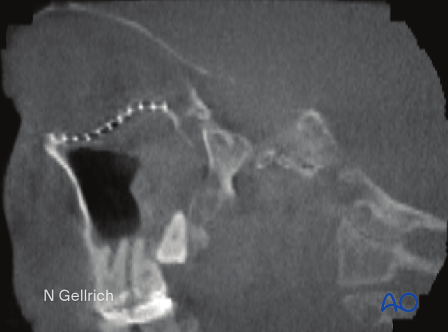
- Intact bone around the defect. The most important is the posterior ledge: the back edge of the defect, on which the implant must rest.
- The medial edge and the lateral floor.
- The infraorbital nerve marks the middle of the floor.
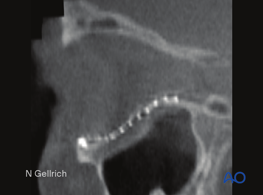
- The floor is not flat. It dips behind the rim and then rises behind the globe. The implant must follow this curve.
Where do I start, and in what order?
- Forced duction test before starting.
- Expose the rim. Dissect along intact bone at the sides of the defect, then lift the herniated tissue out of the sinus.
- Find the posterior ledge.
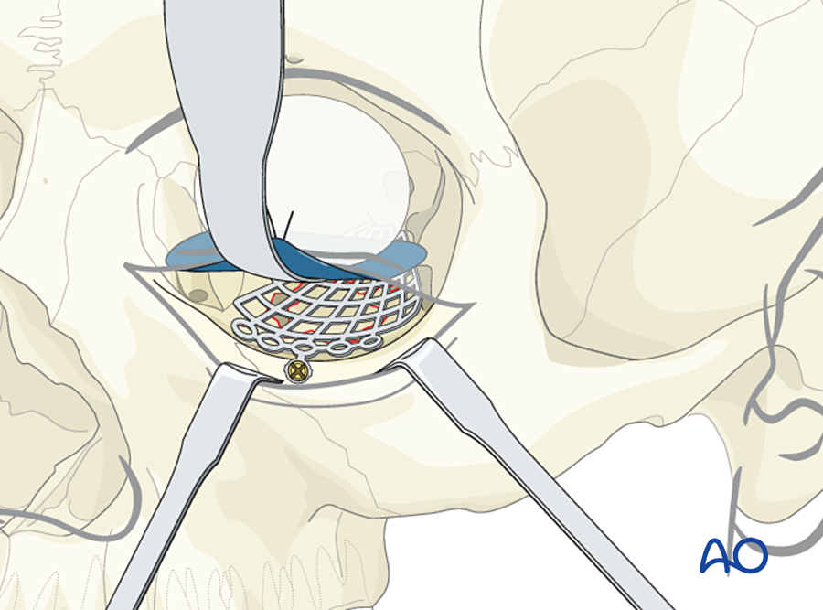
- Place the implant on the ledge, covering the whole defect, behind the rim.
- Fix it with one or two screws at the rim.
Approach
- Transconjunctival (with or without lateral canthotomy), subciliary or subtarsal incision.
- Transcaruncular for the medial wall.
How do I check before closing?
- Forced duction test again: the implant must not trap tissue.
- Globe position.
- Pupil.
- Postoperative CT.
(Burnstine 2002; Jordan 1998)
F. Le Fort fractures
When do I plate?
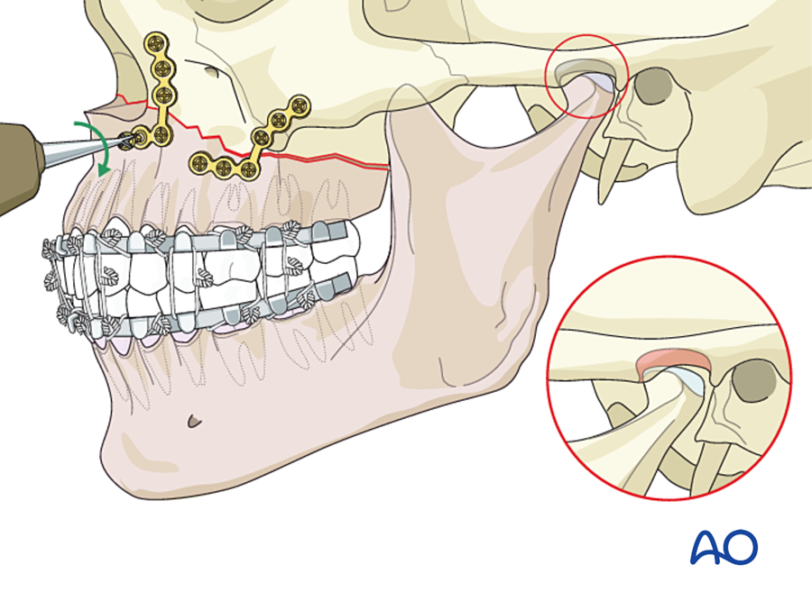
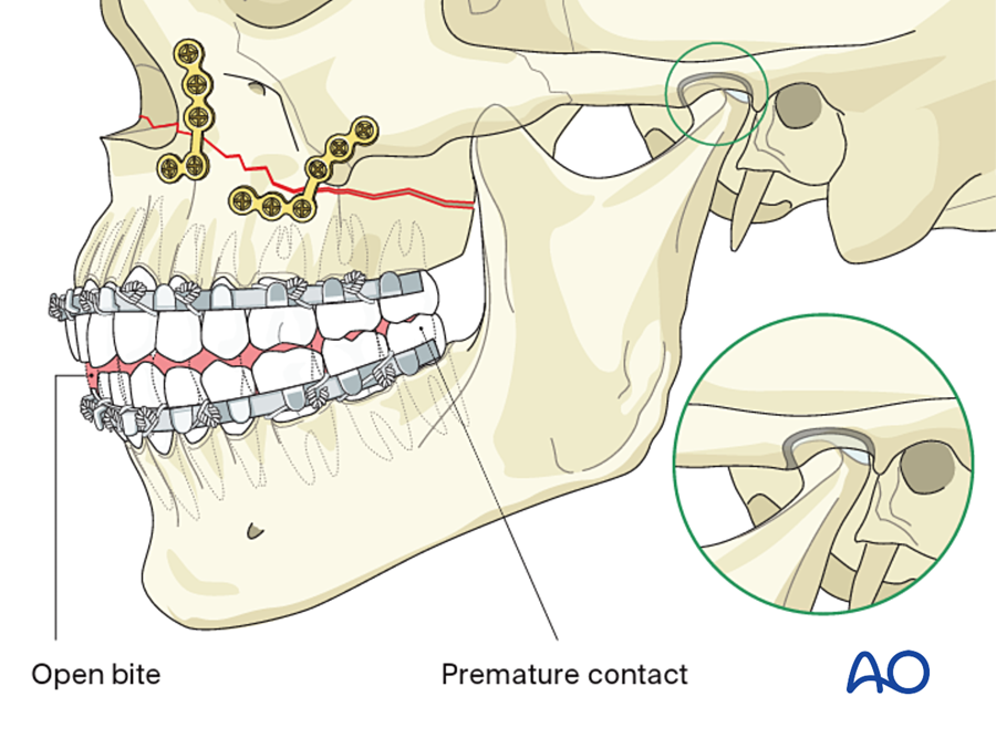
- Mobile maxilla with malocclusion. Typically an anterior open bite, because the maxilla is displaced backward and downward.
- A long or flat midface.
When is it treated without plating?
- Undisplaced or impacted, stable fracture with normal occlusion.
What are my reference points?
- The occlusion against an intact or already-repaired mandible.
- The buttresses on each side: piriform rim and zygomatic buttress.
- For Le Fort II and III: the nasofrontal junction, the orbital rims and the zygomaticofrontal sutures.
Where do I start, and in what order?
- Mobilize the maxilla fully (disimpaction forceps).
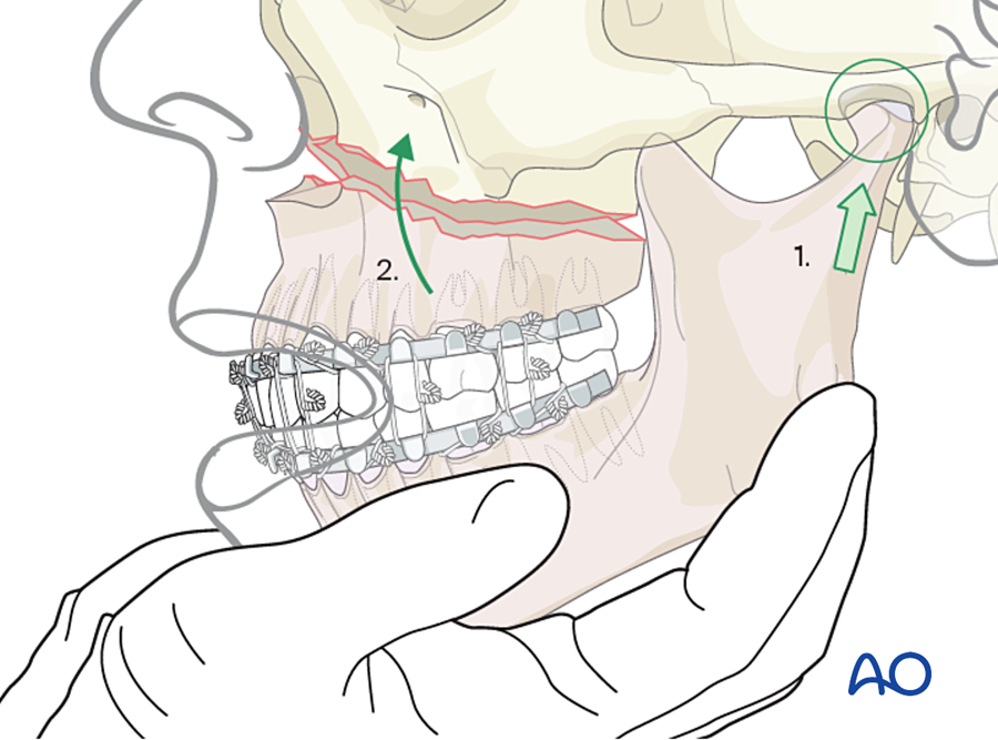
- MMF. The maxilla and mandible now move as one block.
- Rotate the block upward with the condyles seated, until the buttresses meet.
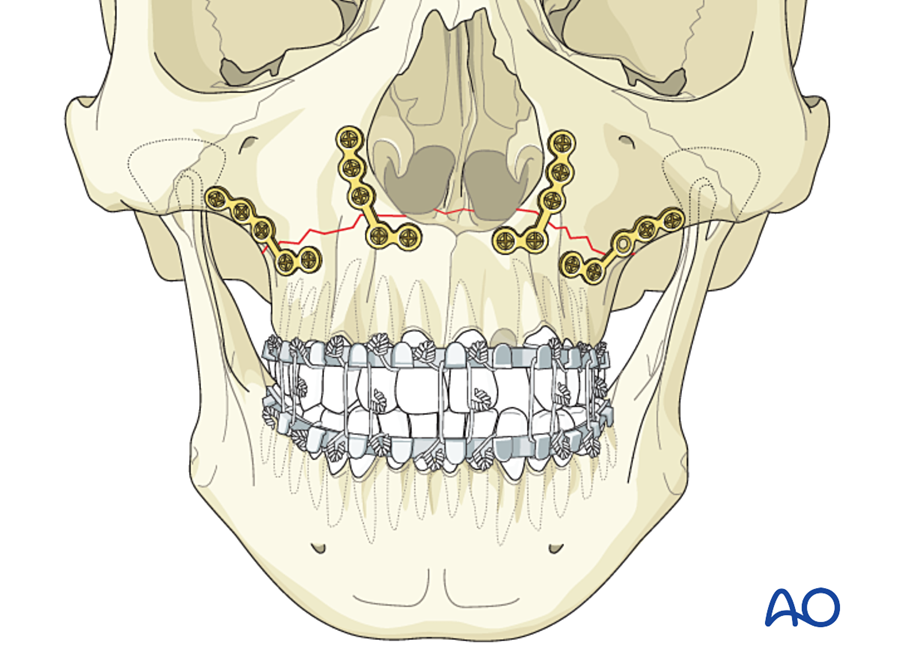
- Plate the four buttresses, starting on the side with the best bone contact.
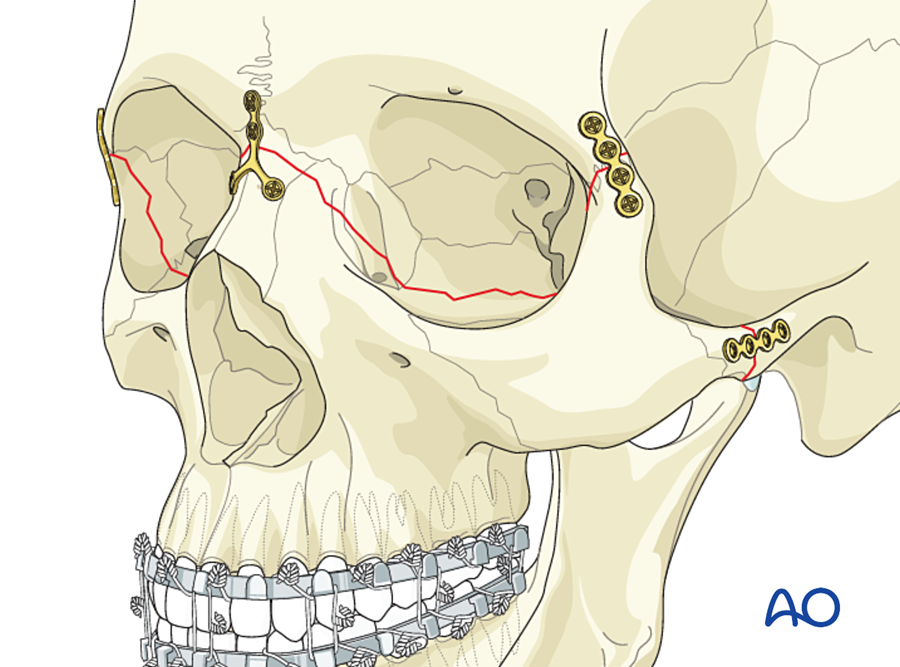
- Le Fort II and III: fix from the stable skull downward (zygomaticofrontal sutures and nasofrontal junction first), then the Le Fort I level.
- Bone graft buttress gaps.
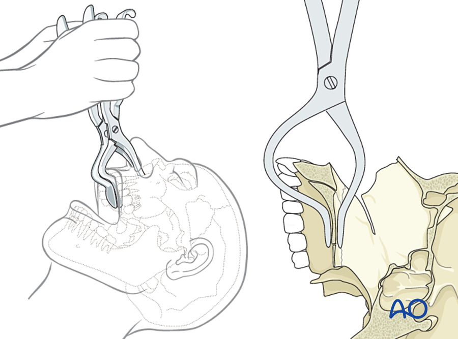
Approach
- Upper buccal sulcus incision for Le Fort I.
- Add lower eyelid and coronal incisions for Le Fort II and III.
How do I check before closing?
- Release the MMF and check the occlusion with the condyles seated.
- An open bite at this point means the condyles were pulled out of the fossae during fixation. Remove the plates, repeat the MMF, seat the condyles and plate again.
G. Naso-orbito-ethmoid (NOE)
When do I plate?
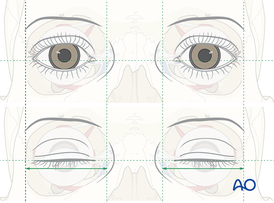
- Telecanthus. An intercanthal distance over about 35 mm suggests it and over 40 mm confirms it. The normal distance is about half the distance between the pupils.
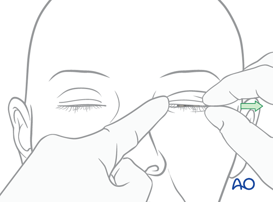
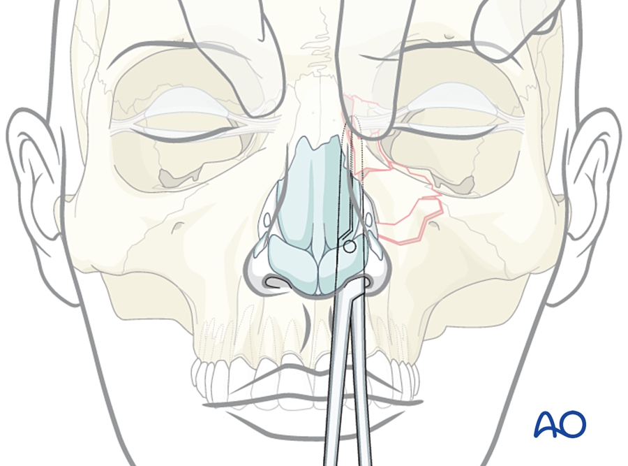
- A central fragment that moves on bimanual examination.
- A flat or shortened nose.
When is it treated without plating?
- Undisplaced fracture with a stable central fragment and normal intercanthal distance.
What are my reference points?
- The intercanthal distance.
- The central fragment that carries the medial canthal tendon.
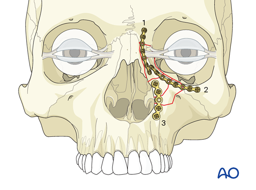
- Its three connections: to the frontal bone above, to the infraorbital rim at the side, and to the piriform rim below.
Where do I start, and in what order?
- Identify the central fragment and the tendon.
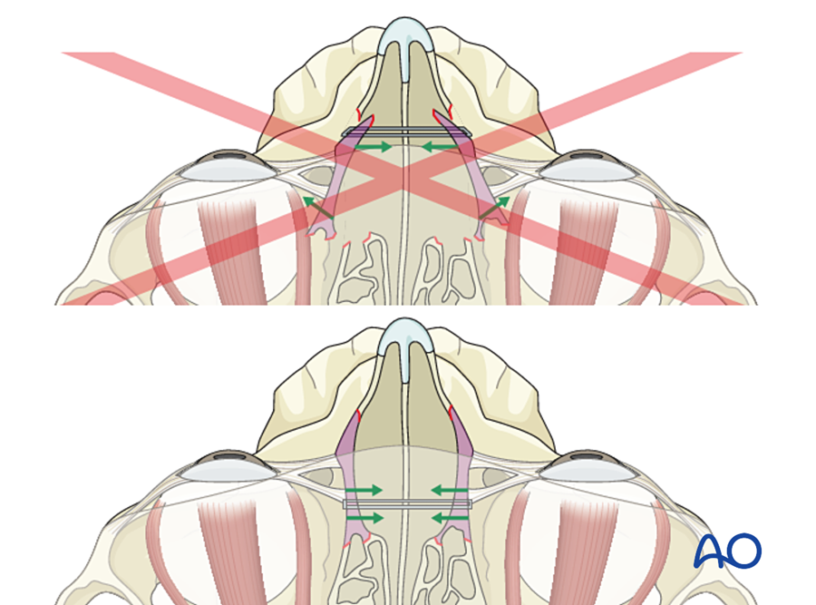
- Set the intercanthal width first, with a transnasal wire through the central fragments (or transnasal canthopexy in type III). Aim for slight over-correction.
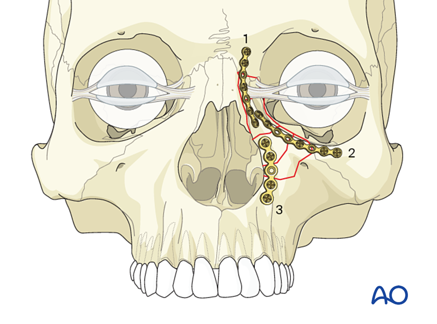
- Plate the central fragment to the frontal bone, the infraorbital rim and the piriform rim.
- Reconstruct the medial orbital wall.
- Restore nasal height with a dorsal bone graft if needed.
- Place soft tissue bolsters over the medial canthal area.
Approach
- Coronal, lower eyelid and upper buccal sulcus incisions.
- Or an existing laceration.
How do I check before closing?
- Measure the intercanthal distance.
- Nasal projection.
- Consider the lacrimal drainage.
H. Frontal sinus
What decides the treatment?
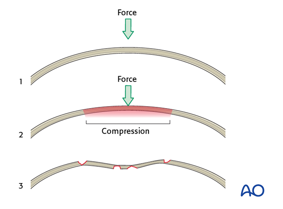
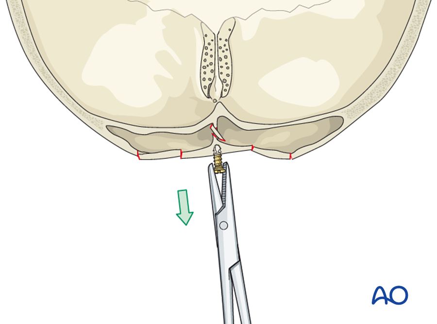
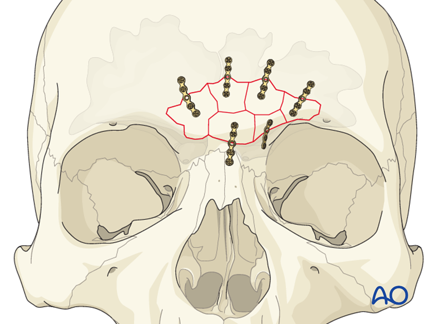
- Anterior table displaced by more than about the thickness of the table: there is a contour deformity. Reduce and plate.
- Nasofrontal outflow tract injured or blocked: obliterate the sinus.
- Posterior table displaced by more than the thickness of the table, or persistent CSF leak: cranialize.
- Undisplaced anterior table fracture with a patent outflow tract: no surgery.
What are my reference points?
- The contour of the surrounding intact frontal bone.
- The supraorbital rims.
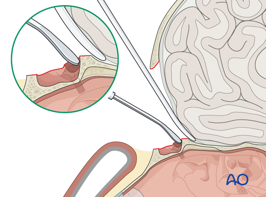
Where do I start, and in what order? (anterior table)
- Lift the fragments.
- Check the outflow tract.
- Replace the fragments.
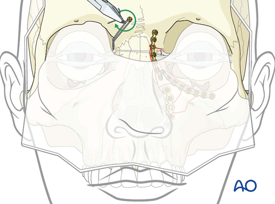
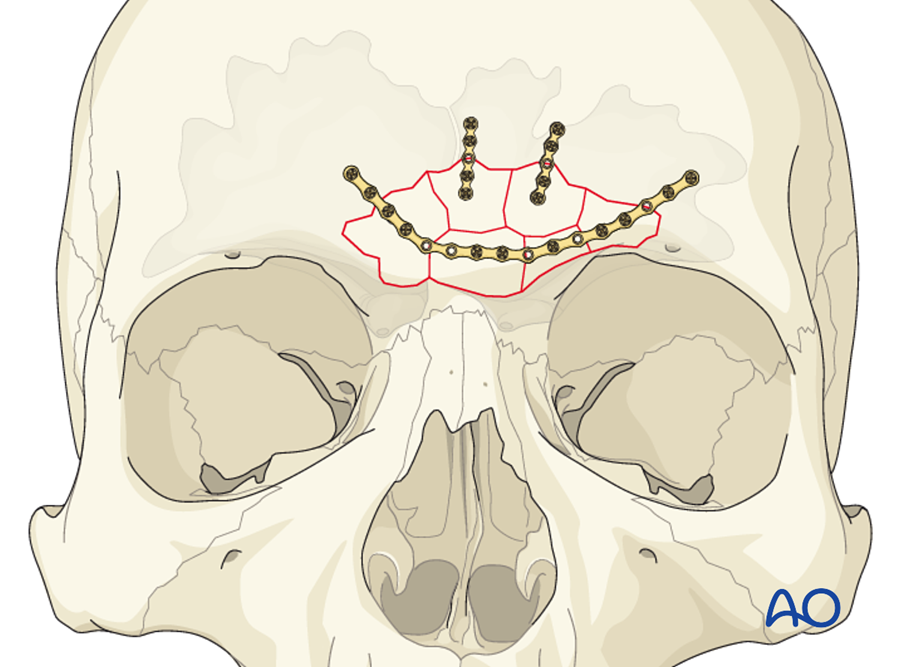
- Fix with microplates or mesh, working from the stable edge inward.
Approach
- Coronal incision.
- Or through a laceration.
How do I check?
- Contour before closing.
- Follow-up CT for aeration of the sinus.
(Rodriguez 2008; Stanwix 2010)
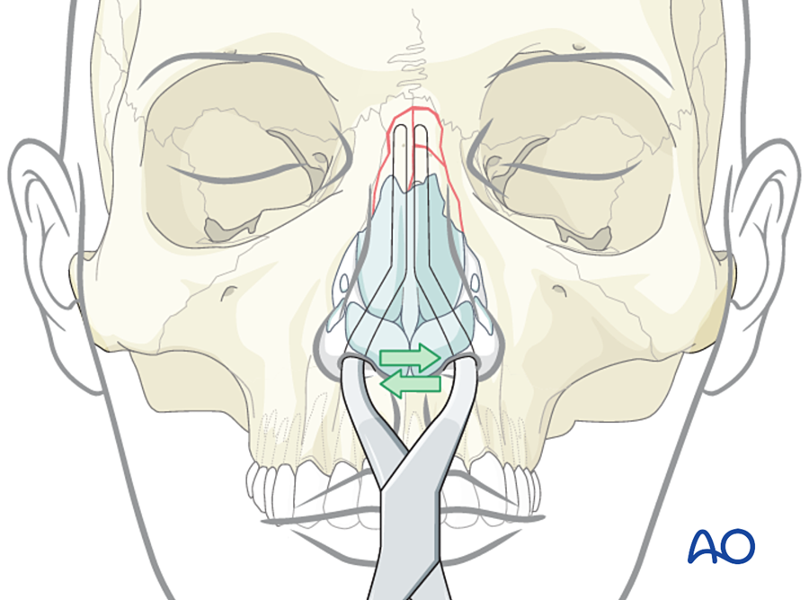
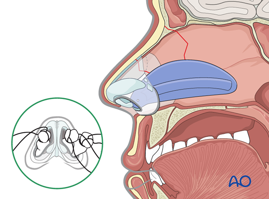
I. Nasal bones
Main points
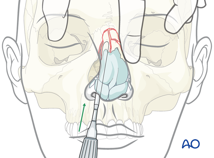
- Nasal fractures are not plated.
- Closed reduction for deviation or obstruction, within 1 to 2 weeks (earlier in children).
- Drain a septal hematoma at once.
- Reference points: the midline and the opposite side.
- Order: reduce the septum, then the nasal bones. Apply internal and external splints.
- Check: the dorsum is in the midline and the airway is open on each side.
J. Panfacial fractures: where do I start?
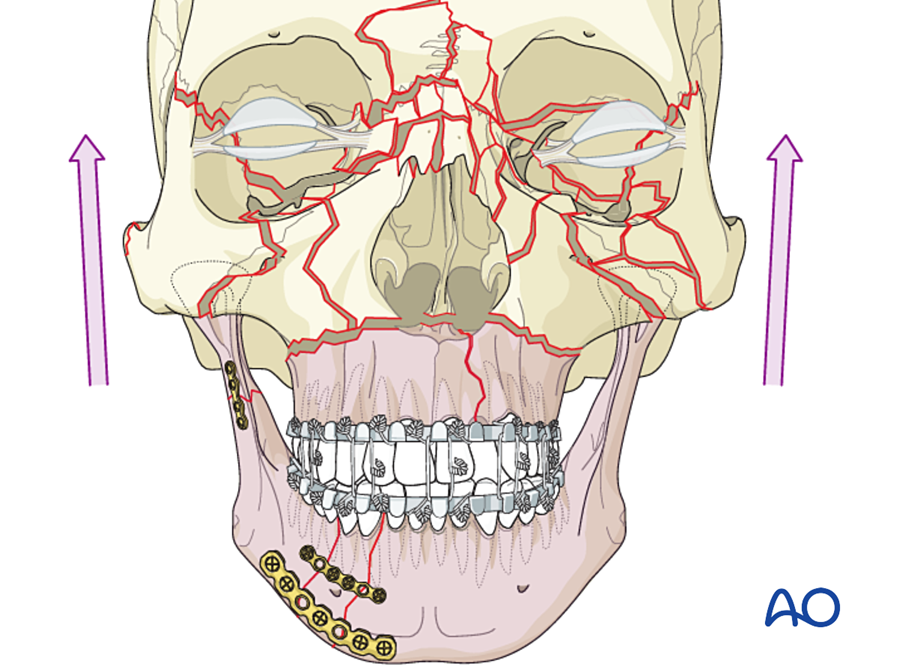
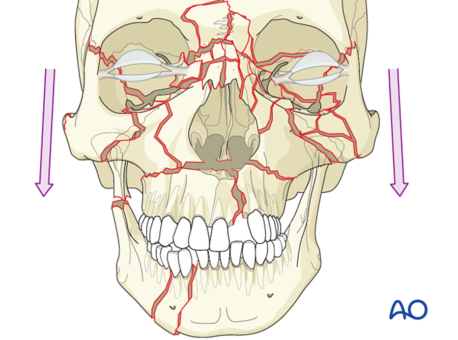
When the mandible, midface and frontal bone are all fractured, there is no intact neighbor to use as a guide. The surgeon has to build one. There are three accepted sequences. All of them use the same rule: start with what can be reduced exactly.
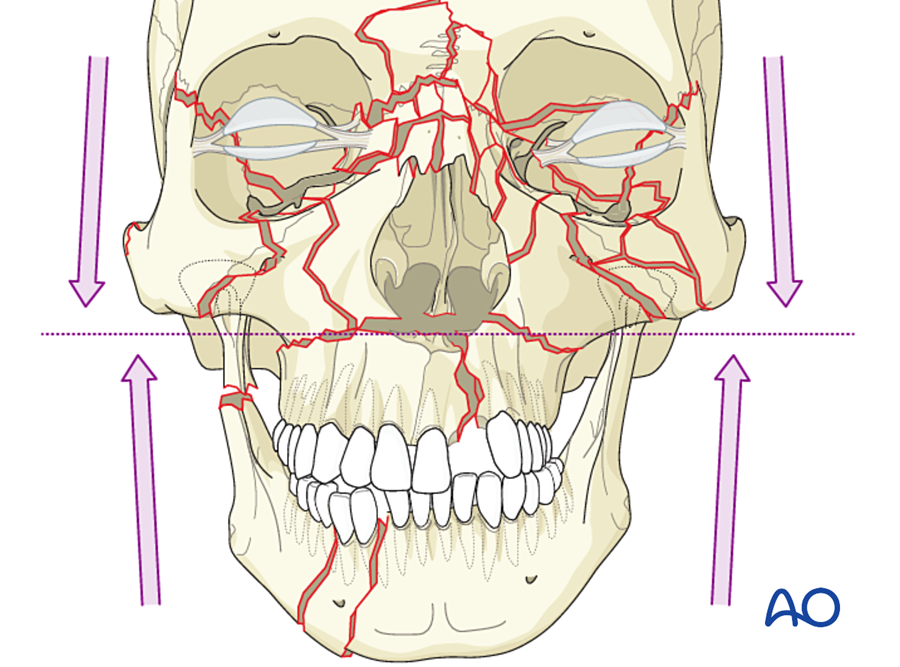
A commonly used order (bottom-up), with the reference point for each step
- Airway and arch bars. Submental intubation or tracheostomy if MMF and nasal surgery are both needed.
- Dental arches. Repair the palate if it is split, and the mandibular arch. Reference: occlusion; dental arch form; mandibular width (angles pressed in).
- MMF, then the mandible. Fix the mandible, including the condyles if they are fractured, to restore posterior facial height. Reference: occlusion; lower border; ramus height.
- Frontal bone and frontal bar. Reference: intact skull.
- Zygomatic arches and zygomas, the outer frame of the midface. Reference: skull base (arch root) and sphenozygomatic suture. This step sets width and projection.
- NOE region. Reference: frontal bar; intercanthal distance.
- Le Fort I level. Join the upper and lower halves by plating the buttresses, with the condyles seated. Reference: occlusion and buttress height. This step sets facial height.
- Orbital walls, nasal dorsum, bone grafts for gaps. Reference: orbital ledges; opposite orbit.
- Soft tissue resuspension and closure. Release the MMF and check the occlusion.
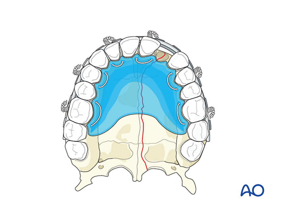
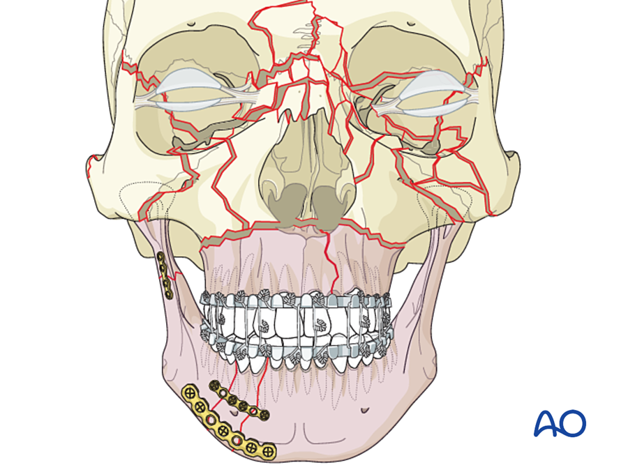
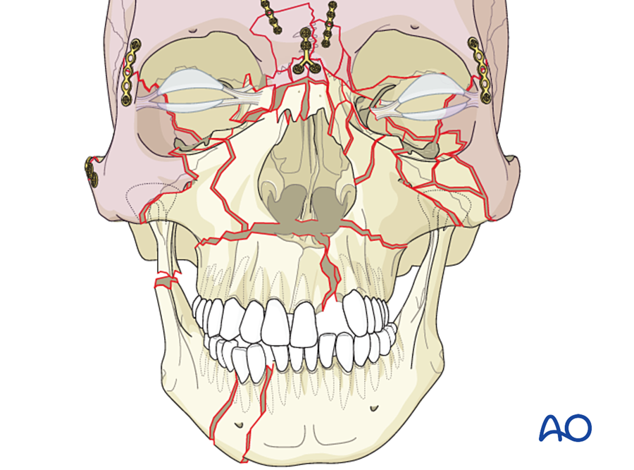
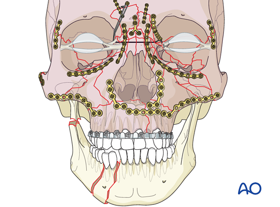
The order of steps 2 to 7 can be reversed ("top-down") when the mandible is too badly damaged to use as a guide. (Markowitz and Manson 1989)
7B.6.3 Why the face is different from a long bone
| Feature of the facial skeleton | Consequence for fixation |
|---|---|
| Thin bone, especially in the midface (often 1 to 2 mm) | Small, low-profile plates and short monocortical screws |
| Low load in the upper and middle face; high load only in the mandible | Microplates and miniplates are enough except in the mandible |
| Membranous bone with very good blood supply | Heals fast, with little callus; infection is less common than expected for a contaminated field |
| The teeth | The occlusion is the reference for reduction. A 1 mm error is noticed by the patient. Screws must avoid roots. |
| Nerves inside the bone (inferior alveolar, infraorbital) | Monocortical screws near the canal; plates placed in safe zones |
| Approach through the mouth or through hidden incisions | Plates must be placed through limited access; fractures are open to saliva |
| Thin soft tissue cover and visible contour | Plates must be thin to avoid being palpable or visible |
| Three-dimensional shape: width, height, projection | The buttresses must be restored in the correct order |
| Growth in children | Avoid rigid metal plates across sutures; avoid tooth buds |
7B.6.4 Implants and instruments
| System | Screw diameter | Plate thickness (about) | Where used | Function |
|---|---|---|---|---|
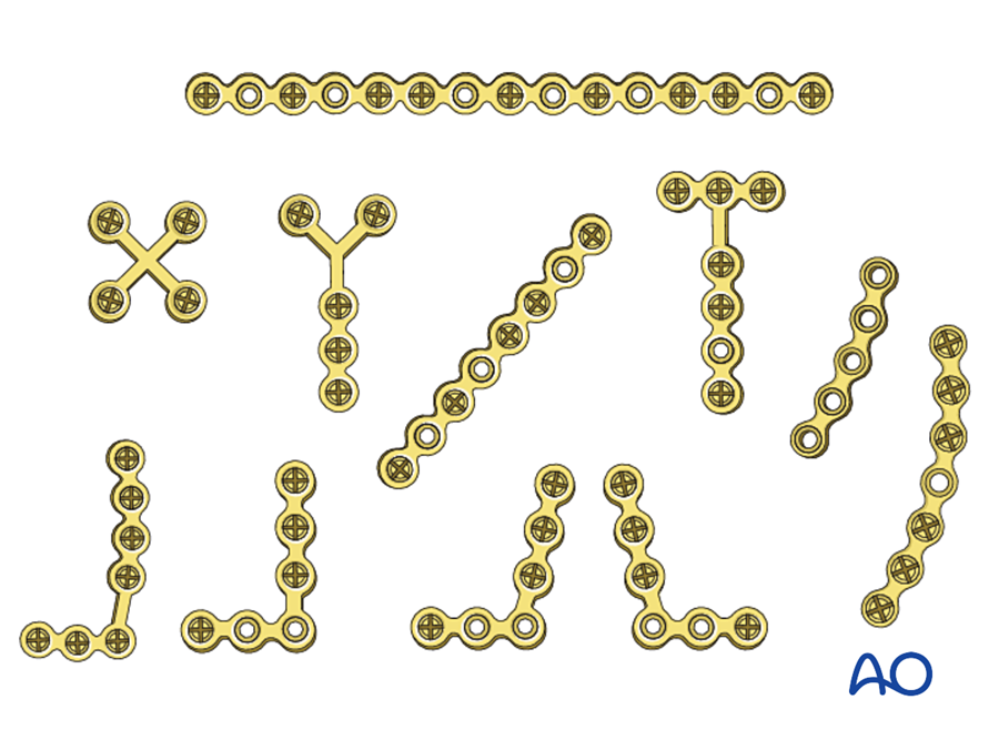
| Microplate | 1.0 to 1.3 mm | 0.4 to 0.6 mm | Naso-orbito-ethmoid region, frontal sinus wall, orbital rim, nasal bones, infant skull | Holds position; almost no load |
| Midface miniplate | 1.5 to 2.0 mm | 0.6 to 1.0 mm | Zygoma, maxillary buttresses, Le Fort fractures and osteotomies | Buttress reconstruction |
| Mandible miniplate | 2.0 mm | 1.0 to 1.5 mm | Simple mandibular fractures (Champy lines); fibula flap segments | Load-sharing (tension band) |
| Reconstruction plate | 2.4 to 3.0 mm, usually locking | 2.0 to 3.0 mm | Comminuted, atrophic, infected mandible; defects; free flap reconstruction | Load-bearing (bridge) |
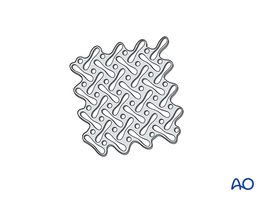
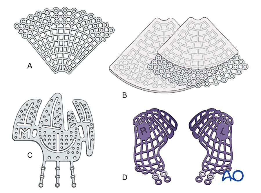
| Mesh and orbital plates | 1.0 to 1.5 mm | 0.2 to 0.6 mm | Orbital floor and walls; cranial defects; comminuted anterior maxilla | Restores contour |
7B.6.5 Occlusion and maxillomandibular fixation (MMF)
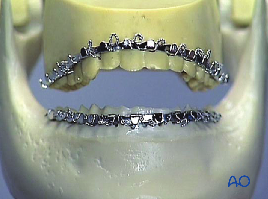
The first step in fixing any fracture that involves the teeth is to place the teeth in correct occlusion and hold them there. This is maxillomandibular fixation (MMF), also called intermaxillary fixation (IMF).
| Method | Description | Advantages | Disadvantages |
|---|---|---|---|
| Arch bars (Erich) | A metal bar wired to the teeth of each jaw; the jaws are joined by wires or elastics | Stable; acts as a tension band along the teeth; allows elastics after surgery | Slow to apply; needle-stick risk; gingival injury; needs teeth |
| IMF screws (bone-supported) | 4 to 8 self-drilling screws in the alveolar bone, joined by wires | Fast; less gingival injury | Root injury; no tension band effect; unsuitable for long-term MMF or comminuted fractures |
| Ernst ligatures, eyelet (Ivy) loops | Wire loops around pairs of teeth | Quick, for temporary fixation | Less stable |
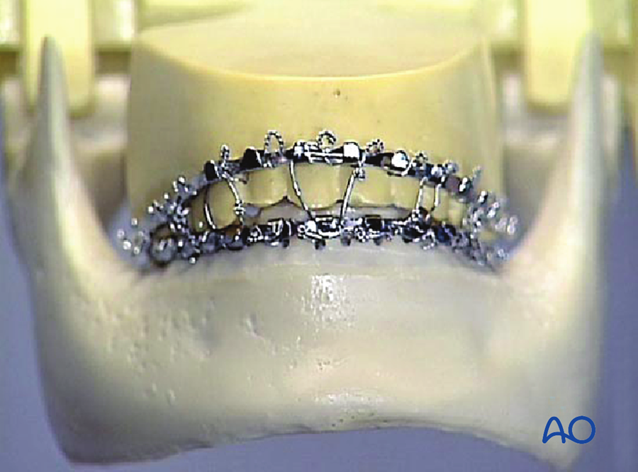
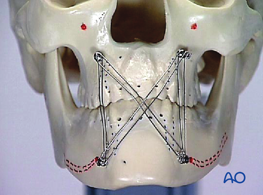
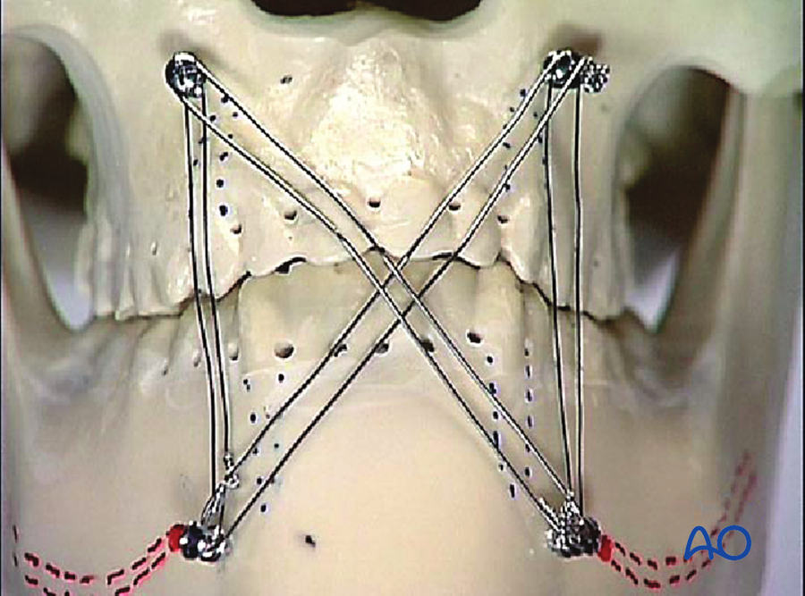
- MMF as temporary fixation: used during surgery to hold the occlusion while plates are applied, then released. This is the usual practice with miniplates.
- MMF as definitive (closed) treatment: about 4 to 6 weeks in adults for a mandibular body fracture; about 2 weeks, followed by guiding elastics, for condylar fractures (to avoid ankylosis); shorter in children.
- Risks of prolonged MMF: airway risk, weight loss, poor oral hygiene, stiffness of the temporomandibular joint.
7B.6.6 Biomechanics of the mandible
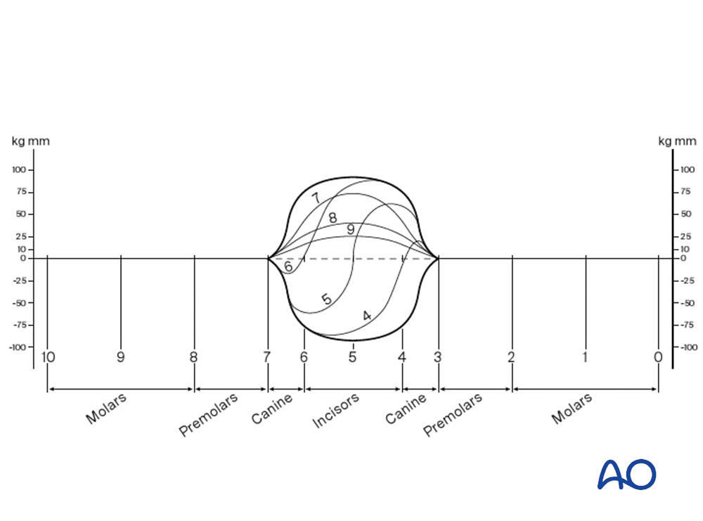
The mandible is the only facial bone under high functional load. During biting:
- the upper border (alveolar side) is under tension: the fracture tends to open there;
- the lower border is under compression;
- in front of the canines, there is also torsion.
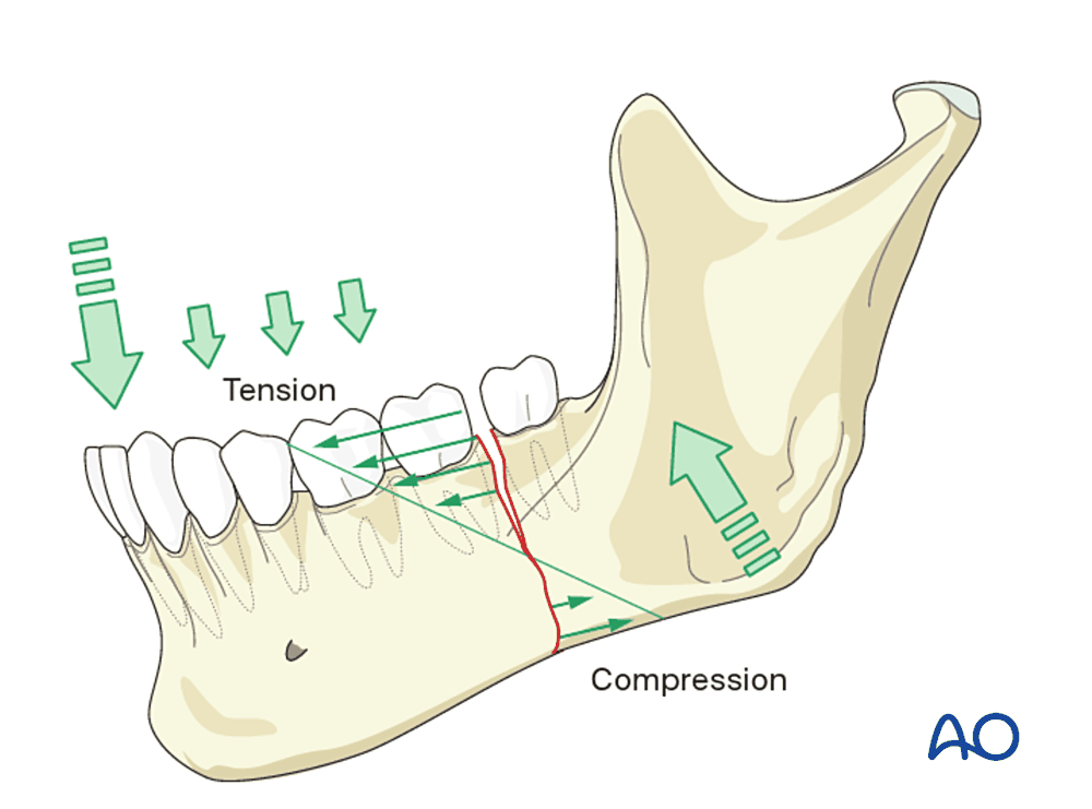
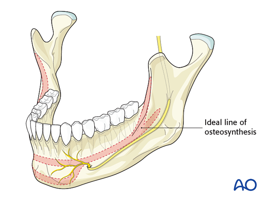
Champy's ideal lines of osteosynthesis. Michelet (1973) and Champy (1978) showed that a small plate placed along the tension zone, with monocortical screws, is enough. The bone itself resists compression at the lower border. The lines are:
- Angle: one plate on the external oblique ridge.
- Body (behind the mental foramen): one plate just below the root tips and above the nerve canal.
- Symphysis and parasymphysis (between the mental foramina): two plates, 4 to 5 mm apart, to resist torsion.
Load-sharing and load-bearing. This is the most important decision in mandibular fixation.
Flowchart: Choosing fixation for a mandibular fracture
- Mandibular fracture
- Can the bone share the load?simple fracture, good bone contact, no infection
- Yes: load-sharing
- Symphysis: 2 miniplates or 2 lag screws
- Body: 1 miniplate
- Angle: 1 miniplate on the oblique ridge
- No: load-bearingcomminuted, defect, atrophic, infected
- Locking reconstruction plate3 or more screws each side
- External fixator
- Yes: load-sharing
- Condyle
- Closed: MMF and elastics
- Open: two miniplates
- Can the bone share the load?simple fracture, good bone contact, no infection
7B.6.7 Fixation of the mandible by region
| Region | Standard fixation | Alternatives | Points to note |
|---|---|---|---|
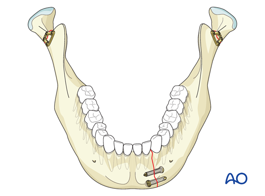
| Symphysis, parasymphysis | Two 2.0 mm miniplates (upper monocortical, lower bicortical) | Two lag screws; one miniplate with an arch bar as the upper tension band | Torsion. Mental nerve. Overbend the plate slightly so the lingual cortex does not gape, which would widen the mandible. |
| Body | One 2.0 mm miniplate below the roots | Lag screws for an oblique fracture; second plate at the lower border if unstable | Inferior alveolar nerve and tooth roots |
| Angle | One 2.0 mm miniplate on the external oblique ridge, through the mouth | Plate on the lateral surface with the transbuccal system; two plates; 3D (strut) plate | Highest complication rate of all mandibular sites. Decide about a third molar in the fracture line. |
| Condylar neck and subcondylar | Closed treatment, or open reduction with two miniplates | One stronger plate; special condylar plates; endoscopic approach | Facial nerve. See below. |
| Comminuted; defect; infected | Locking reconstruction plate, 3 or more screws each side | External fixator | Load-bearing |
| Edentulous atrophic | Locking reconstruction plate, often with primary bone graft | Load-bearing. Poor blood supply. |
(a) Symphysis and parasymphysis
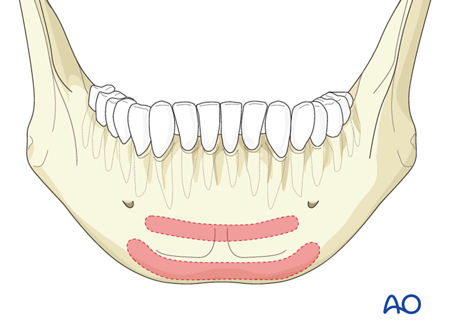
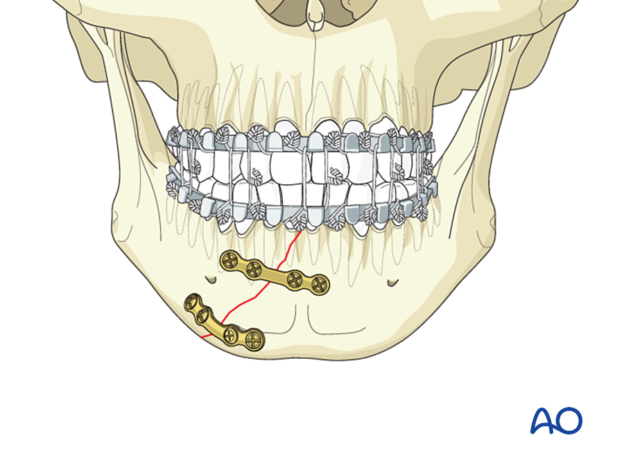
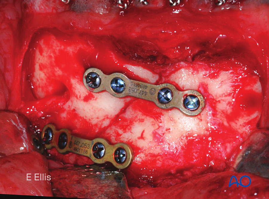
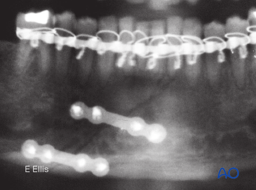
The alternative is two lag screws, which work well here because the curve of the symphysis allows a long screw path through thick cortical bone.
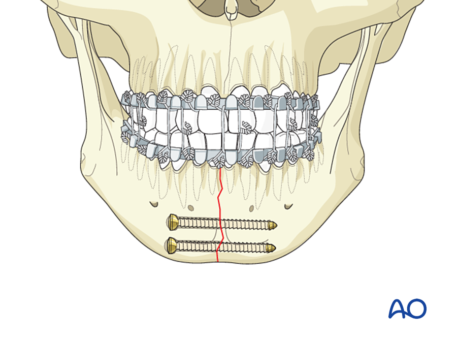
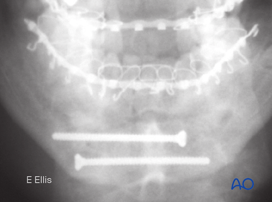
(b) Body
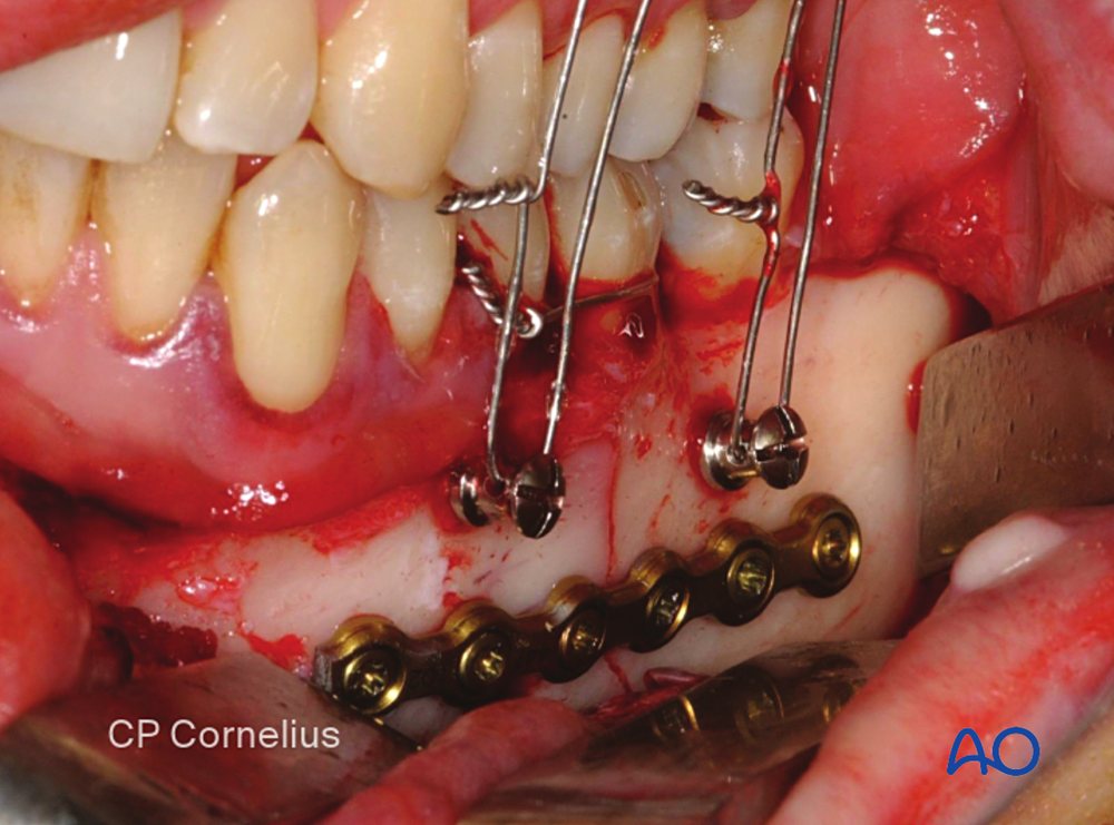
(c) Angle
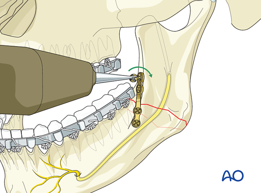
- Ellis (1999) compared eight methods of treating angle fractures in one unit. A single non-compression miniplate at the upper border had the fewest complications. More rigid methods (two plates, compression plates) had more.
- Tooth in the line of fracture: a tooth is kept if it is healthy and helps reduction. It is removed if it is loose, fractured, carious, has periapical infection, or prevents reduction.
(d) Condyle
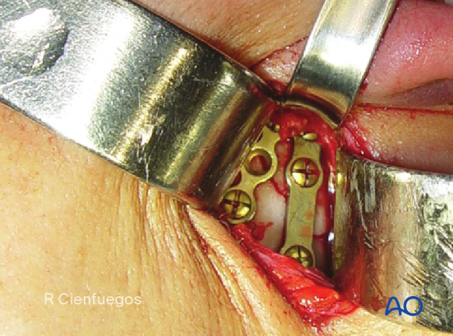
- Most condylar fractures can be treated closed: short MMF, then guiding elastics and early movement.
- Absolute indications for open reduction (Zide and Kent): displacement into the middle cranial fossa; occlusion cannot be obtained by closed treatment; lateral extracapsular displacement of the condyle; foreign body in the joint.
- Open reduction is increasingly used for displaced neck and subcondylar fractures with ramus shortening of 2 mm or more or angulation over 10°. A randomized multicenter trial found better function after open treatment in such fractures (Eckelt 2006).
- Two miniplates are used, because a single miniplate may bend or break under the pull of the lateral pterygoid.
(e) Comminuted, infected and atrophic fractures
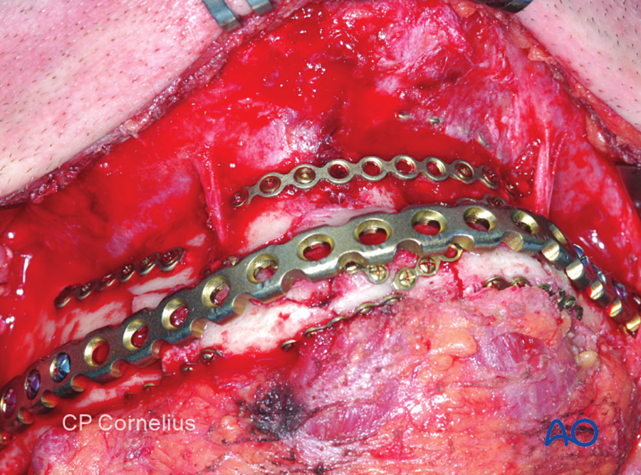
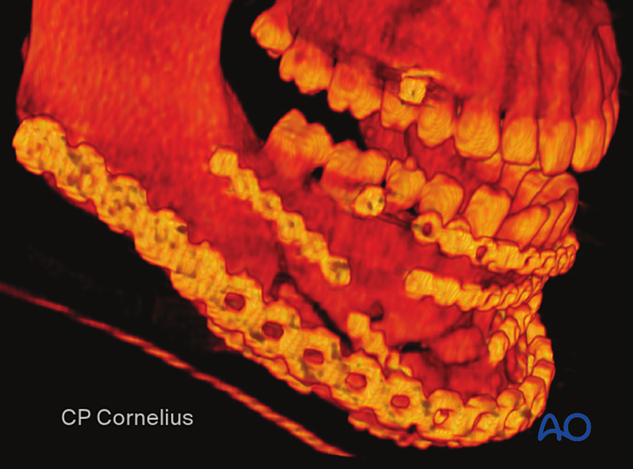
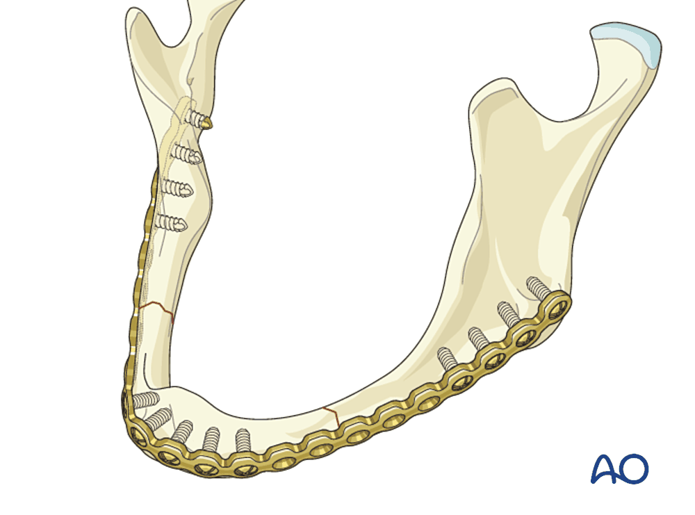
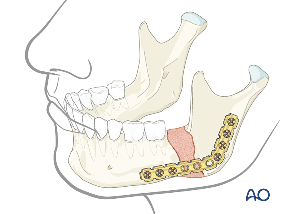
- Atrophic mandible (Luhr classification by bone height): class I 16 to 20 mm; class II 11 to 15 mm; class III 10 mm or less. The thinner the bone, the poorer its blood supply (it depends on the periosteum) and the higher the risk of nonunion. Fixation is load-bearing, with minimal periosteal stripping, and bone graft is often added.
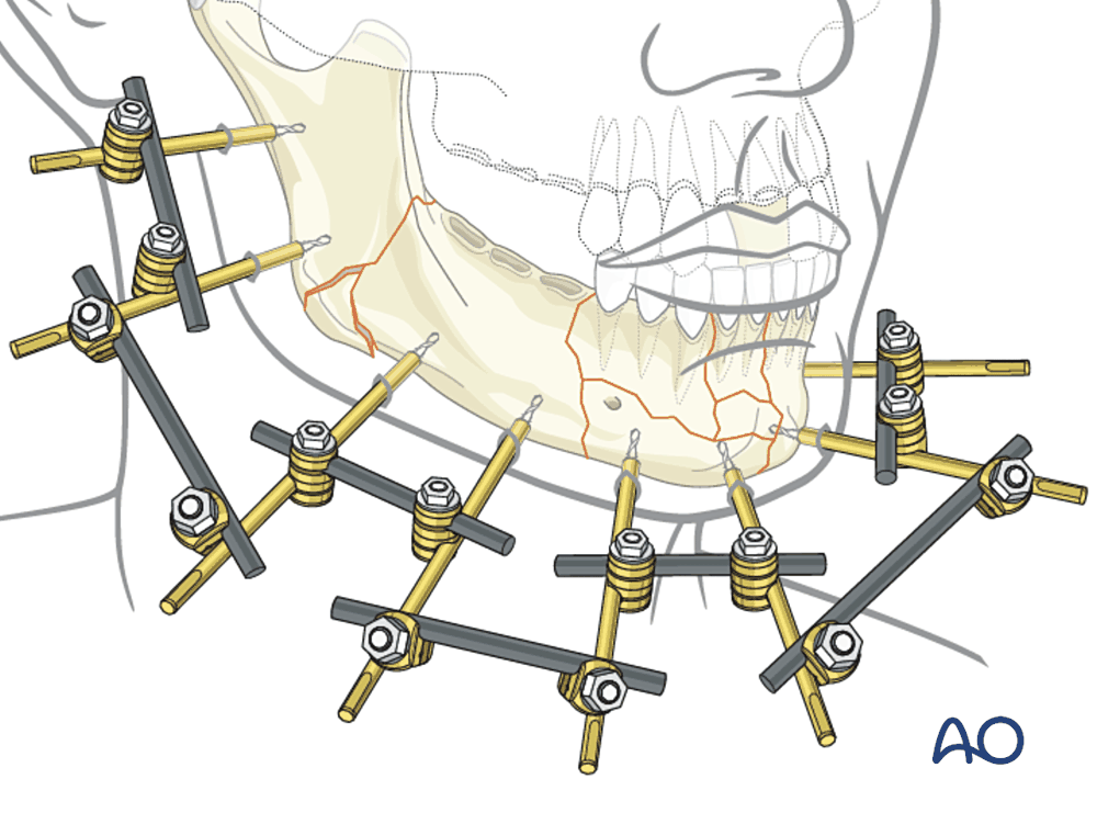
- Infected fracture: the cause is nearly always movement. Treatment is debridement, removal of loose hardware and dead teeth, rigid load-bearing fixation, and bone graft if there is a gap. Stable fixation allows bone to heal even in the presence of infection.
- External fixation is an alternative for gunshot injuries, severe contamination and gross comminution.
7B.6.8 Fixation of the midface
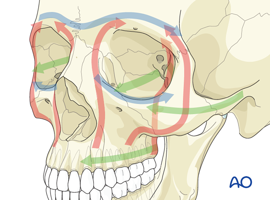
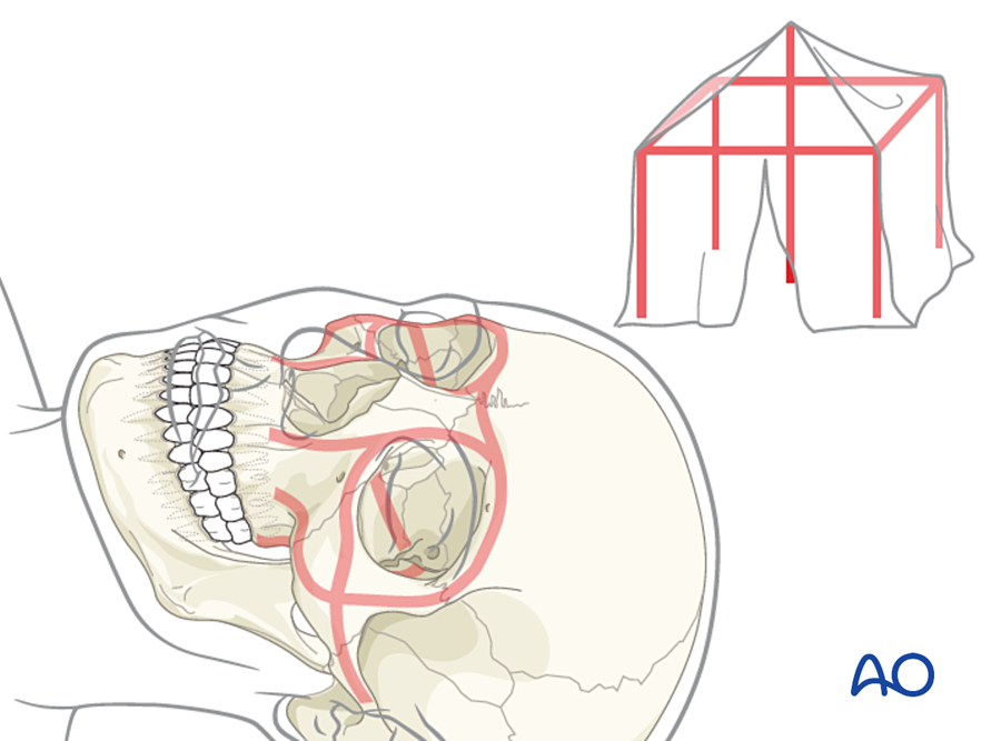
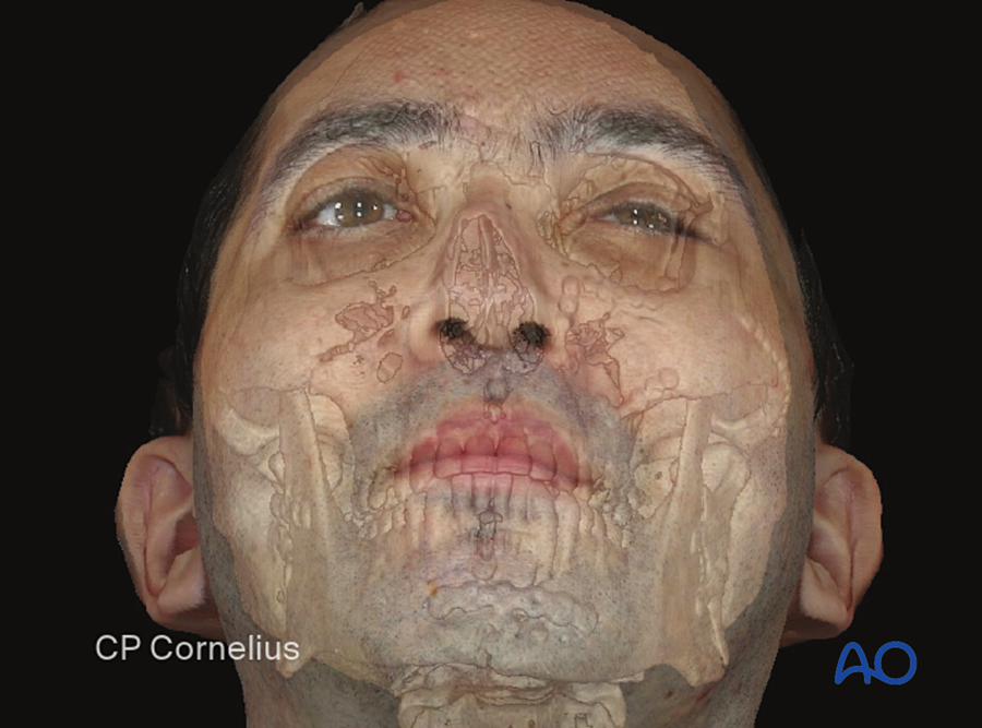
The midface carries much less load than the mandible. The aim is to restore its shape (height, width and projection) by rebuilding the buttresses.
| Vertical buttresses (carry chewing force to the skull base) | Horizontal buttresses (give width and projection) |
|---|---|
| Nasomaxillary (medial): along the piriform rim to the frontal bone | Frontal bar and supraorbital rims |
| Zygomaticomaxillary (lateral): from the first molar through the zygoma to the frontal bone | Infraorbital rims and zygomatic arches |
| Pterygomaxillary (posterior): not accessible for plating | Maxillary alveolus and palate |
(a) Le Fort fractures
| Level | Fracture line | Points of fixation |
|---|---|---|
| Le Fort I | Horizontal, above the tooth roots: separates the palate and alveolus | Four plates: both nasomaxillary (piriform) and both zygomaticomaxillary buttresses. 1.5 to 2.0 mm L-plates. |
| Le Fort II | Pyramidal: nasofrontal area, medial orbit, infraorbital rim, zygomaticomaxillary buttress | Zygomaticomaxillary buttresses, infraorbital rims, nasofrontal junction |
| Le Fort III | Craniofacial separation: nasofrontal, orbits, zygomaticofrontal sutures, arches | Zygomaticofrontal sutures, nasofrontal junction, zygomatic arches (through a coronal approach) |
The occlusion is set first (MMF), then the maxilla is plated to the stable bone above. Gaps in a buttress of more than about 5 mm are bone grafted (Gruss and Mackinnon 1986).
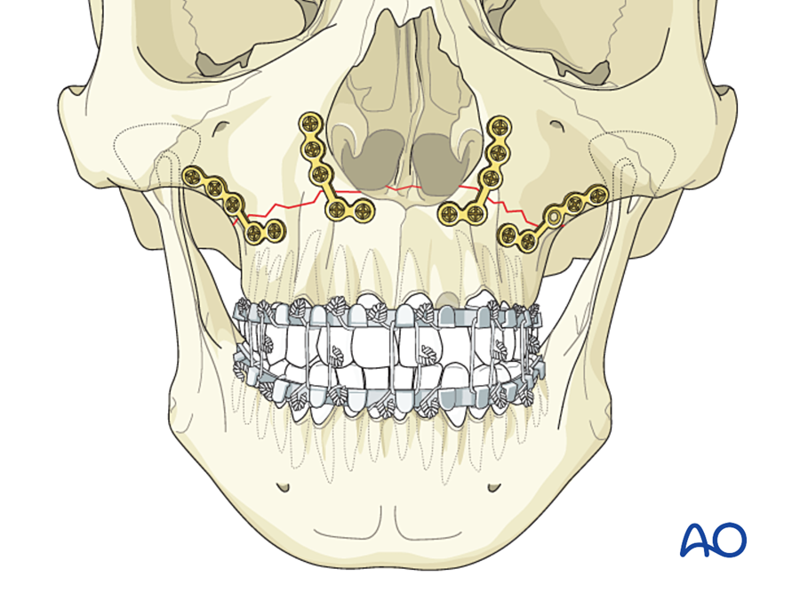
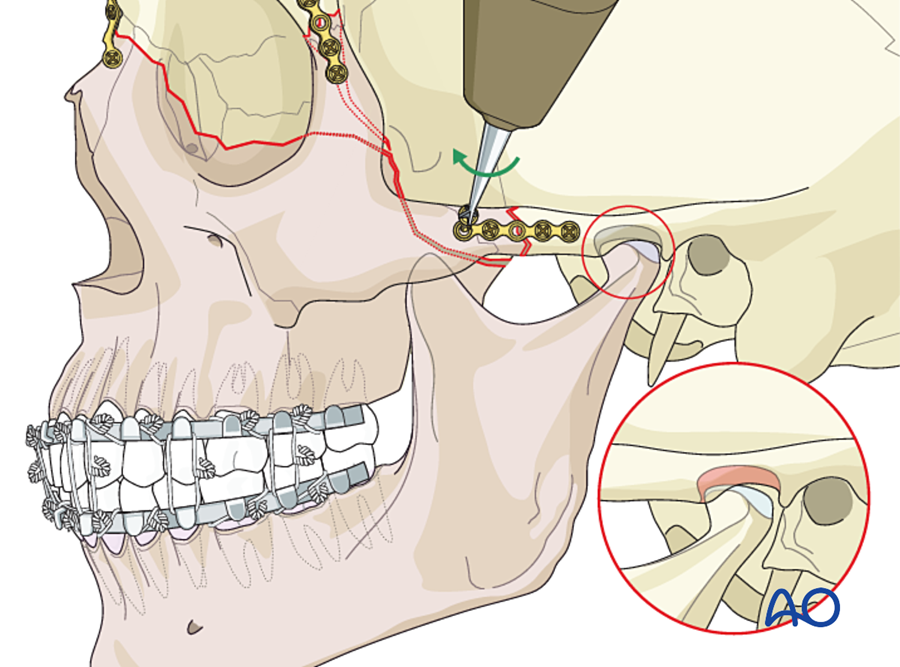
(b) Zygomaticomaxillary complex (ZMC) fracture
- The zygoma joins four bones: frontal, sphenoid (lateral orbital wall), maxilla and temporal (arch).
- The sphenozygomatic suture in the lateral orbital wall is the most reliable guide to correct reduction in three dimensions.
- Points of fixation: (1) zygomaticofrontal suture, (2) infraorbital rim, (3) zygomaticomaxillary buttress, (4) zygomatic arch.
- The number of plates depends on stability after reduction: one point for a simple, stable fracture; two or three for displaced fractures; four (with a coronal approach to the arch) for comminuted, high-energy fractures.
- Isolated arch fractures are usually reduced through a temporal (Gillies) approach and are stable without fixation.
- The orbital floor is explored and reconstructed when the defect is significant.
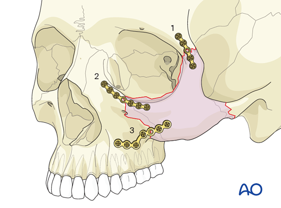
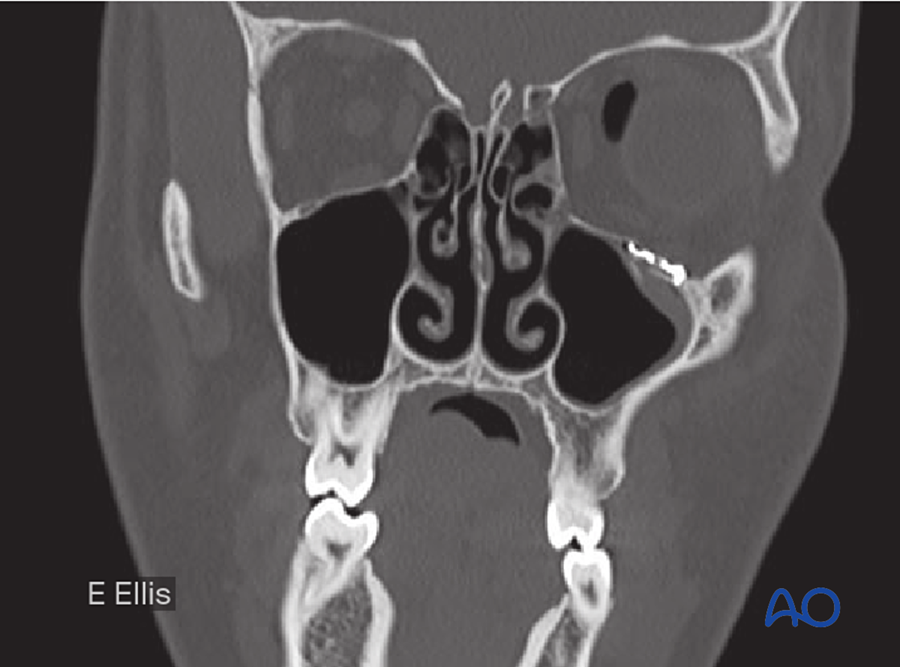
(c) Orbital floor and medial wall
- The orbital walls carry no load. The implant restores the shape and volume of the orbit.
- The implant must rest on the intact posterior ledge and follow the upward slope of the posterior floor. A flat implant leaves the orbit too large (enophthalmos).
- Materials: titanium mesh or preformed orbital plates, porous polyethylene, resorbable sheets, split calvarial bone.
- The implant is fixed with one or two screws at the rim, or it sits stable by its shape.
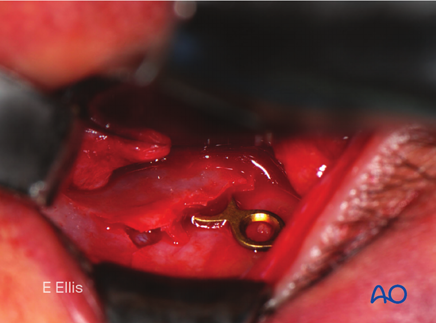
(d) Naso-orbito-ethmoid (NOE) fractures
| Markowitz type | Central fragment (carrying the medial canthal tendon) | Treatment |
|---|---|---|
| I | Single large fragment | Microplates or miniplates to the frontal bone, infraorbital rim and piriform rim |
| II | Comminuted, but the tendon is attached to a fragment large enough to fix | Plates, with or without transnasal wiring of the fragment |
| III | Severely comminuted; the tendon is detached or its fragment is too small | Transnasal canthopexy; bone graft for the medial wall and nasal dorsum |
(e) Frontal sinus
- Anterior table only, displaced: reduction and microplate or mesh fixation for contour.
- Nasofrontal duct blocked: sinus obliteration (remove the mucosa, block the duct, fill with fat, bone or pericranial flap).
- Posterior table displaced, with dural tear or CSF leak: cranialization (remove the posterior table, repair the dura, block the duct), with neurosurgery.
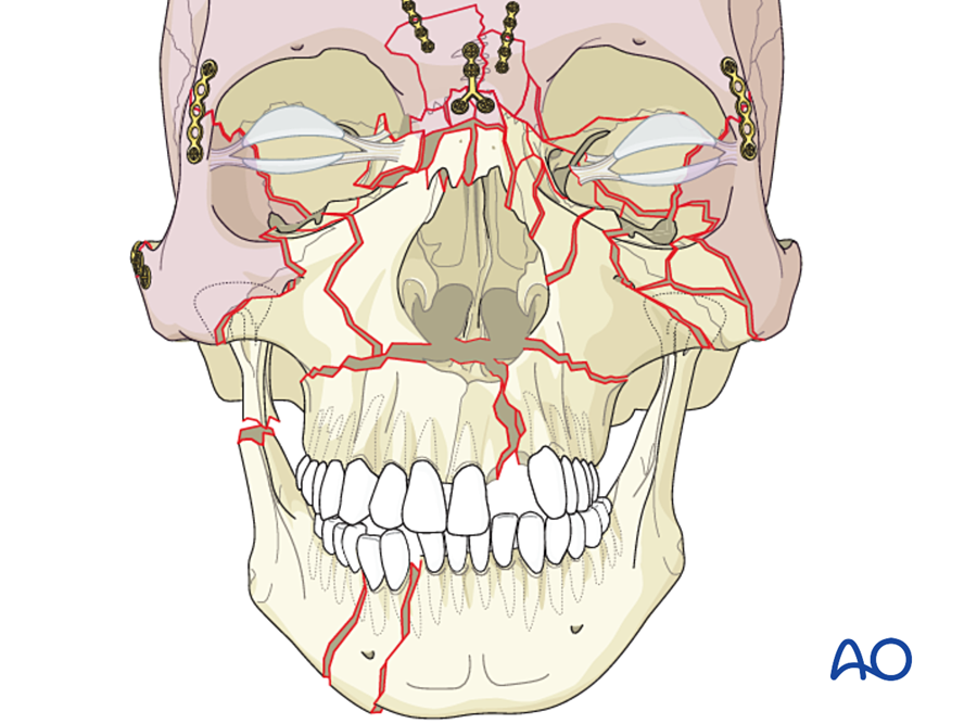
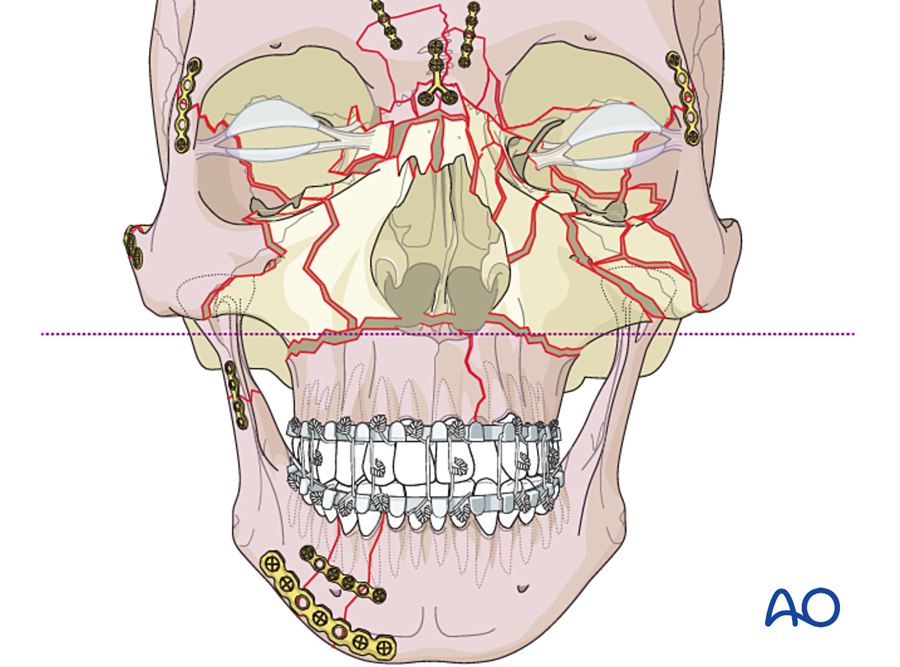
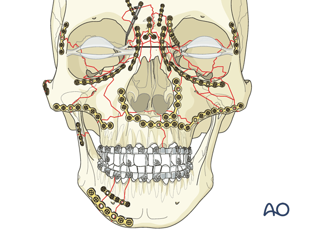
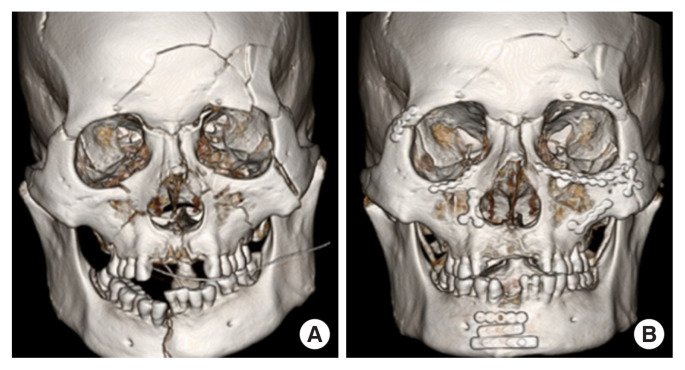
7B.6.9 Panfacial fractures: sequence of repair
A panfacial fracture involves the upper, middle and lower face. There is no stable reference left in the middle, so the face must be rebuilt in order, from stable bone toward unstable bone.
| Sequence | Order | Used when |
|---|---|---|
| "Bottom-up and inside-out" | Occlusion (MMF) → mandible, including condyles → maxilla at Le Fort I level → zygoma and NOE | The mandible can be rebuilt accurately. The mandible then sets the width and projection of the lower face. |
| "Top-down and outside-in" | Frontal bar → zygomatic arches and zygomas (outer frame) → NOE → maxilla → mandible | The skull and zygomatic arches are a more reliable guide, for example with severe mandibular comminution or bilateral condylar fractures |
In practice both are combined. The key steps are the same: set the occlusion, restore facial width first (zygomatic arches, mandibular width), then projection, then height.
7B.6.10 Fixation of osteotomies, bone flaps and bone grafts
| Procedure | Fixation | Reason |
|---|---|---|
| Le Fort I osteotomy | Four 1.5 to 2.0 mm L-plates at the piriform rims and zygomatic buttresses | Same buttresses as a Le Fort I fracture |
| Bilateral sagittal split osteotomy | Three bicortical position screws on each side, or one miniplate with monocortical screws | No compression: protects the nerve and keeps the condyle seated |
| Genioplasty | Pre-bent step plate, or lag screws or wires | Low load |
| Fronto-orbital advancement and vault remodeling in infants | Resorbable plates and screws, or resorbable sutures | Growing skull |
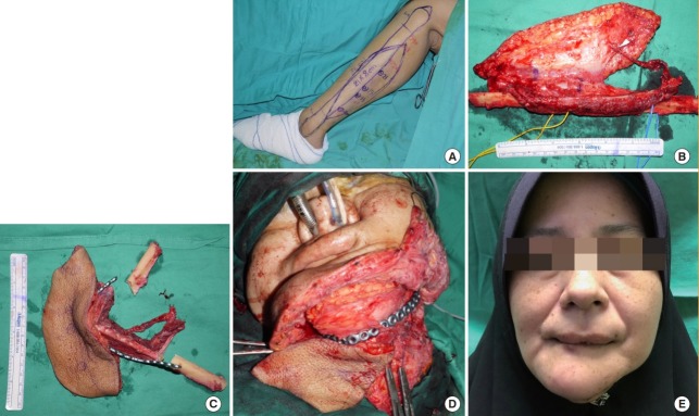
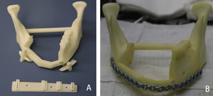
| Free fibula for the mandible | Either one locking reconstruction plate along the whole reconstruction, or 2.0 mm miniplates (two per junction) | See below |
| Onlay and inlay bone grafts | Lag screws or position screws | A graft that moves resorbs |
| Cranial bone flap; calvarial graft donor site | Microplates, clamps; mesh over burr holes | Contour only |
Fixation of a free fibula flap to the mandible:
| Reconstruction plate | Miniplates | |
|---|---|---|
| Advantages | Strong; holds the mandibular segments in their original position (the plate is bent to the native mandible before resection, or is pre-bent or custom-made from the virtual plan); quick | Low profile; less stress shielding; easier to place dental implants later; easier to adjust each segment |
| Disadvantages | Bulky; may be exposed, especially after radiotherapy; stress shielding of the fibula | Less rigid; more screws near the osteotomies; the condylar position must be controlled another way |
| Evidence | No difference in nonunion or overall complications in 117 patients (Robey 2008). Bone contact at each junction matters more. | |
- Screws in the fibula should be monocortical where possible and placed away from the pedicle side, to protect the periosteal blood supply.
- The periosteum is not stripped; only a small window is opened for each plate.
- In irradiated native mandible, use locking screws and at least three or four screws on each side.
7B.6.11 Fixation in children
- Children's facial bone heals fast and remodels well. Many fractures are treated closed or with minimal fixation.
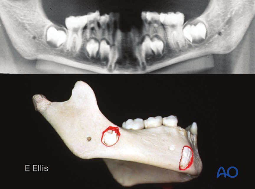
- Tooth buds fill the body of the mandible and the maxilla. Plates are placed at the lower border of the mandible with short monocortical screws.
- Growth: rigid plates across sutures can restrict growth. In infants, metal plates on the skull can move inward with growth and end up inside the skull or on the dura, because bone is laid down on the outer surface and resorbed on the inner surface.
- Resorbable plates (PLLA and PGA copolymers) keep useful strength for about 6 to 8 weeks and resorb over 1 to 3 years. They are thicker than titanium and are shaped after warming. In 1,883 children, problems with the devices that needed reoperation occurred in under 1% (Eppley 2004).
- If titanium plates are used in a growing child, many surgeons remove them after healing.
- MMF is kept short (about 2 weeks) because of the risk of ankylosis.
7B.6.12 Complications of craniofacial fixation
| Complication | Usual cause | Management |
|---|---|---|
| Infection | Unstable fixation; loose screws; dead tooth in the fracture; poor oral hygiene; smoking. Most common at the mandibular angle. | Drain; antibiotics. If the fixation is stable, keep it until union. If loose, remove and replace with load-bearing fixation. |
| Malocclusion | Occlusion not set before plating; plate not bent accurately (non-locking); condyle out of the fossa | Early: revise. Minor: elastics, orthodontics. Late: osteotomy. |
| Nonunion, malunion | Movement; infection; atrophic or irradiated bone | Debride, load-bearing plate, bone graft; vascularized bone if irradiated |
| Nerve injury | Inferior alveolar and mental nerves (screws, retraction); facial nerve (approaches to the condyle and arch); infraorbital nerve | Prevention by screw position and approach |
| Tooth root injury | Screws or IMF screws | Monocortical screws; place between roots |
| Plate exposure | Thin mucosa or skin; radiotherapy; underlying nonunion | Treat the cause; remove after union; flap cover |
| Palpable or visible plate; cold sensitivity | Thin soft tissue (orbital rim, forehead) | Use the thinnest plates there; remove if symptomatic |
| Enophthalmos, diplopia | Orbital volume not restored; implant malposition | Revision |
| Facial widening | Zygomatic arch or mandibular width not restored in panfacial fractures | Prevention by correct sequence |
Routine removal of titanium plates in adults is not necessary.
7B.7 Fixation in the hand
The principles are the same as in the face: small bones, small implants, and a functional aim. In the hand the aim is tendon gliding and joint movement.
| Method | Stability | Advantages | Disadvantages | Typical use |
|---|---|---|---|---|
| K-wires (0.8 to 1.6 mm) | Relative | Percutaneous; little dissection; cheap; removed at 3 to 4 weeks | Not rigid; pin-track infection; may tether tendons; delays active movement | Transverse and short oblique phalangeal and metacarpal fractures; replantation; mallet fractures; arthrodesis |
| Lag screws (1.0 to 2.0 mm) | Absolute | Rigid with small exposure; low profile; early movement | Needs a long oblique or spiral fracture (length at least twice the bone diameter); technically precise | Spiral and long oblique fractures; condylar fractures |
| Plates (1.0 to 2.3 mm; locking available) | Absolute or bridging | Maintains length; rigid | Wide dissection; tendon adhesion; stiffness (36% major complications; Page and Stern 1998) | Comminuted or multiple fractures; bone loss; nonunion; replantation at metacarpal level |
| Interosseous wire; 90-90 wiring; tension band wire | Stable | Low profile; cheap | Needs open exposure | Replantation, arthrodesis, avulsion fractures |
| Intramedullary fixation (K-wires or headless screws) | Relative | Minimal dissection; early movement | Rotational control limited | Metacarpal neck and shaft fractures |
| External fixator (mini) | Relative, adjustable | Away from the injury zone; maintains length | Pin problems; bulky | Open comminuted fractures, bone loss, fracture-dislocations of the proximal interphalangeal joint |
- K-wire rules: two wires to control rotation; crossed wires should not cross at the fracture line; avoid the extensor hood and the joint where possible.
- In replantation the bone is shortened and fixed by the fastest stable method (usually K-wires or interosseous wires), before the tendons, vessels and nerves are repaired.
7B.8 Intramedullary nails and external fixators (brief)
These are applied by orthopedic surgeons. We need to understand them because they decide the blood supply of the bone under our flaps and the access for our surgery.
7B.8.1 Intramedullary nail
- A rod inside the medullary canal, locked by screws at each end. Load-sharing, relative stability, healing with callus.
- Reaming destroys the endosteal blood supply for some weeks. If the periosteum has also been stripped by an open injury, the bone depends on its soft tissue cover. This is one reason early flap cover matters in open tibial fractures.
7B.8.2 External fixator
- Pins or wires through the bone, away from the injury, joined by an external frame. Relative stability, adjustable.
- Types: unilateral (one bar), circular (Ilizarov rings with tensioned wires), hybrid, and hexapod frames. Circular frames are used for bone transport and lengthening, which is distraction osteogenesis.
- Stiffness increases with: larger pin diameter (the main factor), more pins, pins spread apart, the bar closer to the bone, and a second bar or plane.
- Indications: open fractures with severe soft tissue injury, damage control, infection, bone transport; in the face and hand, as noted above.
- Complications: pin-track infection and loosening, neurovascular injury, joint stiffness from pins through muscle, malunion.
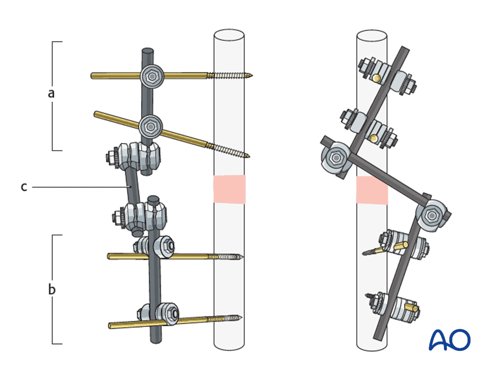
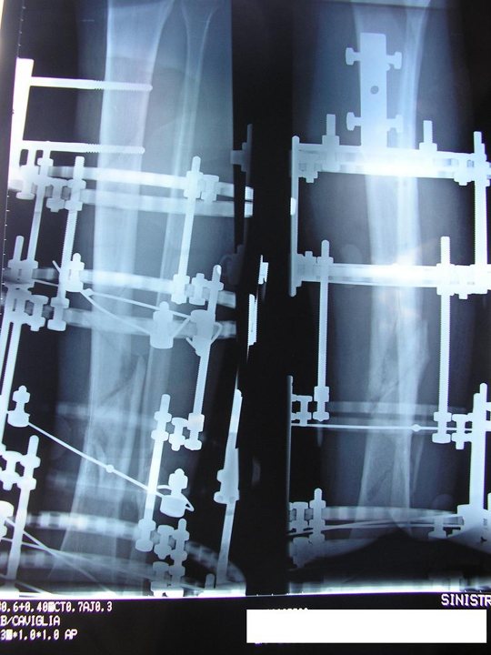
The external fixator and the flap:
- Agree the pin sites with the orthopedic surgeon. Pins and bars should not cross the planned incisions, the pedicle route or the recipient vessels.
- The frame should allow positioning for microsurgery; bars can be moved temporarily.
- After the flap, the frame elevates the limb and protects the flap and anastomosis from pressure and movement.
- Sequence in a Gustilo IIIB tibia: debridement → skeletal stabilization → flap cover within days → bone reconstruction later if needed.
7B.9 Summary
- Fixation gives absolute stability (compression), relative stability (splinting), or, in the face, functionally stable fixation.
- The lag screw is the basic tool of compression. Locking plates act as internal fixators and keep the reduction when the plate does not fit perfectly.
- Mandible: decide between load-sharing (miniplates on Champy's lines) and load-bearing (reconstruction plate). Set the occlusion first.
- Midface: plate the buttresses; restore width, then projection, then height; reconstruct the orbit for volume.
- Children: minimal fixation, resorbable where possible, avoid tooth buds.
- Hand: the least fixation that allows early movement.
References
- Ehrenfeld M, Manson PN, Prein J, eds. Principles of Internal Fixation of the Craniomaxillofacial Skeleton: Trauma and Orthognathic Surgery. Thieme; 2012.
- AO Surgery Reference, CMF (surgeryreference.aofoundation.org/cmf): basic techniques; mandible; midface; skull base and cranial vault. Source of the AO figures in this chapter.
- Buckley RE, Moran CG, Apivatthakakul T, eds. AO Principles of Fracture Management. 3rd ed. Thieme; 2017.
- Michelet FX, Deymes J, Dessus B. Osteosynthesis with miniaturized screwed plates in maxillo-facial surgery. J Maxillofac Surg 1973;1:79–84.
- Champy M, Loddé JP, Schmitt R, Jaeger JH, Muster D. Mandibular osteosynthesis by miniature screwed plates via a buccal approach. J Maxillofac Surg 1978;6:14–21.
- Ellis E. Treatment methods for fractures of the mandibular angle. Int J Oral Maxillofac Surg 1999;28:243–252.
- Ellis E. Use of lag screws for fractures of the mandibular body. J Oral Maxillofac Surg 1996;54:1314–1316.
- Zide MF, Kent JN. Indications for open reduction of mandibular condyle fractures. J Oral Maxillofac Surg 1983;41:89–98.
- Eckelt U, Schneider M, Erasmus F, et al. Open versus closed treatment of fractures of the mandibular condylar process: a prospective randomized multi-centre study. J Craniomaxillofac Surg 2006;34:306–314.
- Luhr HG, Reidick T, Merten HA. Results of treatment of fractures of the atrophic edentulous mandible by compression plating. J Oral Maxillofac Surg 1996;54:250–254.
- Manson PN, Hoopes JE, Su CT. Structural pillars of the facial skeleton. Plast Reconstr Surg 1980;66:54–62.
- Gruss JS, Mackinnon SE. Complex maxillary fractures: role of buttress reconstruction and immediate bone grafts. Plast Reconstr Surg 1986;78:9–22.
- Markowitz BL, Manson PN, Sargent L, et al. Management of the medial canthal tendon in nasoethmoid orbital fractures. Plast Reconstr Surg 1991;87:843–853.
- Robey AB, Spann ML, McAuliff TM, et al. Comparison of miniplates and reconstruction plates in fibular flap reconstruction of the mandible. Plast Reconstr Surg 2008;122:1733–1738.
- Eppley BL, Morales L, Wood R, et al. Resorbable PLLA-PGA plate and screw fixation in pediatric craniofacial surgery: clinical experience in 1883 patients. Plast Reconstr Surg 2004;114:850–856.
- Egol KA, Kubiak EN, Fulkerson E, et al. Biomechanics of locked plates and screws. J Orthop Trauma 2004;18:488–493.
- Wagner M. General principles for the clinical use of the LCP. Injury 2003;34 Suppl 2:B31–B42.
- Page SM, Stern PJ. Complications and range of motion following plate fixation of metacarpal and phalangeal fractures. J Hand Surg Am 1998;23:827–832.
- Fragomen AT, Rozbruch SR. The mechanics of external fixation. HSS J 2007;3:13–29.
- Ellis E, Kittidumkerng W. Analysis of treatment for isolated zygomaticomaxillary complex fractures. J Oral Maxillofac Surg 1996;54:386–400.
- Zingg M, Laedrach K, Chen J, et al. Classification and treatment of zygomatic fractures: a review of 1,025 cases. J Oral Maxillofac Surg 1992;50:778–790.
- Manson PN, Markowitz B, Mirvis S, Dunham M. Toward CT-based facial fracture treatment. Plast Reconstr Surg 1990;85:202–212.
- Burnstine MA. Clinical recommendations for repair of isolated orbital floor fractures: an evidence-based analysis. Ophthalmology 2002;109:1207–1210.
- Jordan DR, Allen LH, White J, Harvey J. Intervention within days for some orbital floor fractures: the white-eyed blowout. Ophthalmic Plast Reconstr Surg 1998;14:379–390.
- Rodriguez ED, Stanwix MG, Nam AJ, et al. Twenty-six-year experience treating frontal sinus fractures: a novel algorithm based on anatomical fracture pattern and failure of conventional techniques. Plast Reconstr Surg 2008;122:1850–1866.
- Stanwix MG, Nam AJ, Manson PN, Mirvis S. Critical computed tomographic diagnostic criteria for frontal sinus fractures. J Oral Maxillofac Surg 2010;68:2714–2722.
- Markowitz BL, Manson PN. Panfacial fractures: organization of treatment. Clin Plast Surg 1989;16:105–114.
- Hermund NU, Hillerup S, Kofod T, Schwartz O. Effect of early or delayed treatment upon healing of mandibular fractures: a systematic literature review. Dent Traumatol 2008;24:22–26.