7C.1 Introduction
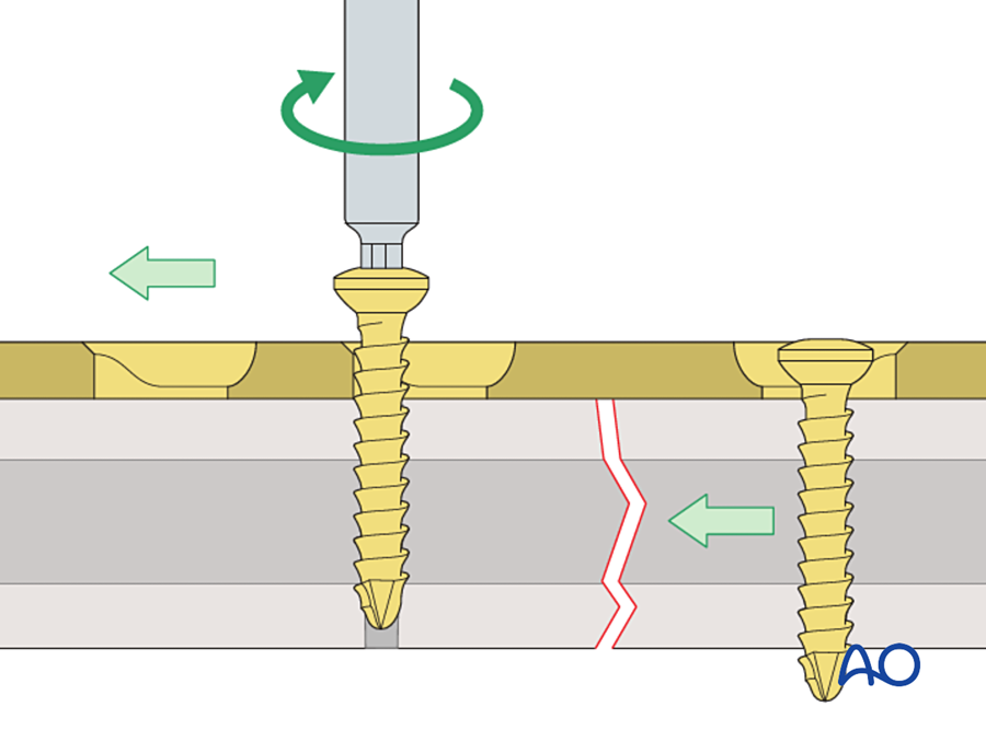
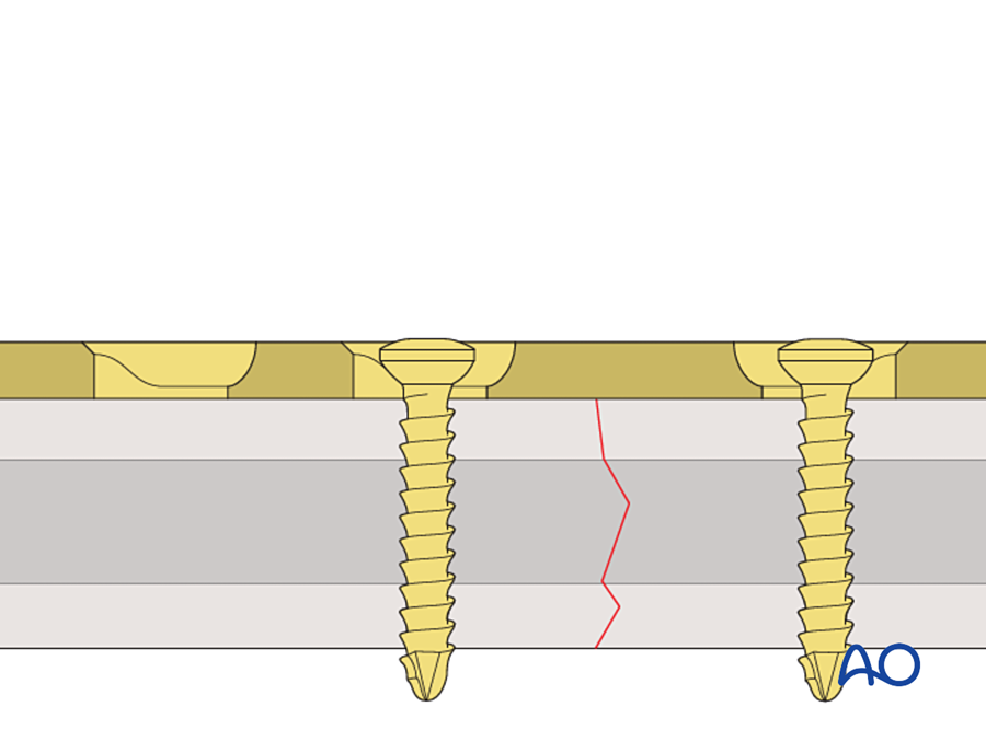
The dynamic compression plate (DCP) is a bone plate with a specially shaped screw hole. When a screw is tightened at one end of the hole, the screw head slides down a slope inside the hole. This movement pushes the bone fragment toward the fracture. The fracture is compressed by the plate and its own screws, and no other instrument is needed.
The DCP was introduced in 1969 by Stephan Perren and the Swiss AO group (Perren 1969; Allgöwer 1970). It is an orthopedic implant, but it matters to plastic surgeons for three reasons:
- Compression plating was the first form of rigid internal fixation used in the mandible. Miniplates, reconstruction plates and locking plates were all developed in response to it.
- The DCP hole is still present in the plates we use today, including small plates for the hand and the "combination hole" of locking plates.
- The story of the DCP explains two ideas that we use every day: absolute stability and primary bone healing.
This chapter answers four questions, in this order: What was the problem? What was tried before? How does the DCP work and why was it an innovation? What were its limits and what replaced it?
Flowchart: Overview of the chapter
- Dynamic compression plate
- The problemfracture disease; plates without compression
- Earlier answers1886 to 1965
- Danis: compression1949
- Bagby: oval hole1956
- Müller: tension device1965
- The DCP1969
- Design of the hole
- Technique
- Why it was an innovation
- Limits and later plates
- LC-DCP1990
- PC-Fix
- LCP2001
- Plastic surgerymandible, hand and forearm, bone flaps
7C.2 The problem before the DCP
To understand why the DCP was important, we first need to understand what fracture treatment was like before it. There were two separate problems. The first was the result of treating fractures without surgery. The second was the failure of the early plates.
7C.2.1 Fracture disease
Until the 1950s most fractures were treated in plaster or in traction for many weeks. The bone usually united. The limb often did not recover. Long immobilization caused stiff joints, muscle wasting, disuse osteoporosis and chronic swelling. This group of problems was called fracture disease. Malunion and shortening were also common.
The solution seemed simple: fix the bone so firmly that the patient can move the joints on the first day, without a cast. For this the fixation must be strong enough to work alone. The early plates were not.
7C.2.2 Why a plate without compression fails
A plain plate with round holes holds the fragments in line. It does not press them together. Three things then happen.
- A small gap remains. Even a well reduced fracture has a gap of a fraction of a millimeter. Strain is movement divided by gap width, so a very small movement in a very small gap gives a high strain. Bone cannot form when strain is above about 2%.
- The bone ends resorb. The body responds to high strain by resorbing the bone ends. This widens the gap and lowers the strain, but now the fragments no longer touch.
- The plate carries all the load. With no contact between the fragments, every load passes through the plate. The plate bends a little with each movement. After many thousands of cycles it loosens or breaks by fatigue.
Compression solves all three. When the two fragments are pressed together, the gap is closed. Friction between the rough bone surfaces stops them from sliding. The bone carries load again and the plate is protected. This is absolute stability.
The compression applied at surgery is called preload. The fracture stays closed as long as the preload is greater than the forces that try to pull it open during function. This is the same principle as a row of books carried by pressing them together from both ends: the row behaves as one solid block until the pressing force is released.
| Plate without compression | Plate with compression | |
|---|---|---|
| Contact between fragments | Incomplete; a gap remains | Full contact under pressure |
| Movement at the fracture | Small, but strain is high because the gap is narrow | None under functional load |
| Who carries the load | The plate alone | Bone and plate together |
| Bone ends | Resorb | Do not resorb |
| Healing | Delayed union, or plate failure before union | Primary healing, without callus |
| External support | A cast is still needed | No cast; joints move early |
So by the 1950s the aim was clear. Surgeons needed a plate that could compress the fracture. The remaining question was how to produce that compression in a simple and reliable way.
7C.3 History leading to the DCP
The DCP was the end of an 80-year series of attempts. Each attempt solved one problem and showed the next one. The table lists them in order.
| Year | Surgeon | What was new | Problem that remained |
|---|---|---|---|
| 1886 | Carl Hansmann, Hamburg | The first bone plate. One end was bent to come out through the skin so the plate could be removed later. He used it in limb fractures and in two mandibular fractures. | Infection and metal corrosion |
| 1895 | William Arbuthnot Lane, London | Steel plate and screws, with a strict "no touch" aseptic technique | The steel corroded in the tissues and the plates loosened |
| 1909 | Albin Lambotte, Antwerp | A thin plate, tapered at both ends. Lambotte also introduced the word "osteosynthesis". | Less corrosion, but too weak |
| 1912 | William Sherman, Pittsburgh | Vanadium steel plate, with a shape designed to reduce stress concentration | Still corroded; still too weak |
| 1930s | Venable and Stuck | Showed that corrosion was an electrolytic reaction between metals. Introduced the inert cobalt-chromium alloy Vitallium. | The metal problem was solved. The mechanical problem was not. |
| 1948 | George Eggers, Texas | A plate with two long slots. The screws could slide, so muscle pull kept the bone ends in contact as they resorbed. | The slotted plate was weak and the fixation was unstable |
| 1949 | Robert Danis, Brussels | The coapteur: a plate with a side screw that compressed the fracture. Danis saw that these fractures healed without callus. He called it soudure autogène (autogenous welding). We now call it primary bone healing. | The device was complex and was used by few surgeons |
| 1956 to 1958 | George Bagby and Joseph Janes, Mayo Clinic | A plate with oval holes. A screw placed at the far end of the hole moved toward the fracture as it was tightened. This was the first self-compressing plate. | Little compression; not developed into a full system; not widely adopted |
| 1958 | Müller, Allgöwer, Willenegger, Schneider, Bandi and colleagues, Switzerland | Founded the AO (Arbeitsgemeinschaft für Osteosynthesefragen). Maurice Müller had visited Danis in 1950. The group set out to make compression fixation standard, with matched implants, instruments, teaching courses and documentation of every case. | A practical compression plate was still needed |
| About 1960 to 1965 | Maurice Müller | A strong, thick (4.5 mm) round-hole plate, compressed with a separate, removable tension device | The tension device itself (see below) |
| 1969 | Stephan Perren and the AO group | The dynamic compression plate: the compression mechanism is built into each hole |
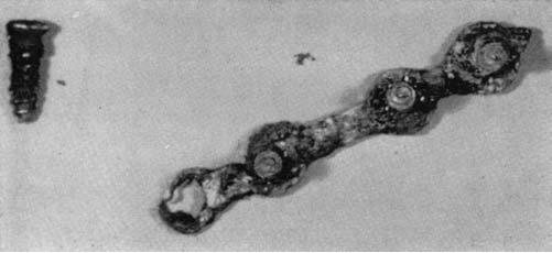
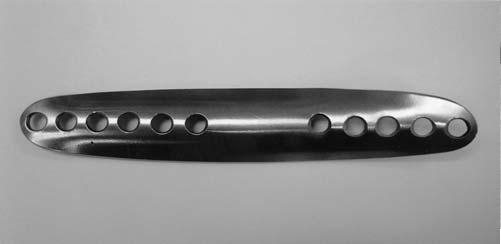
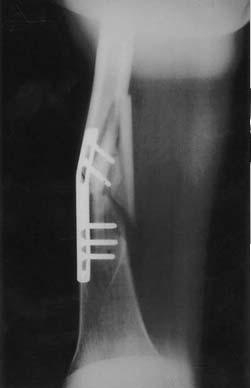
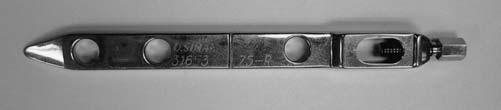
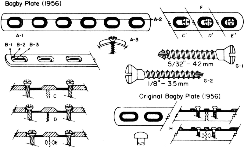
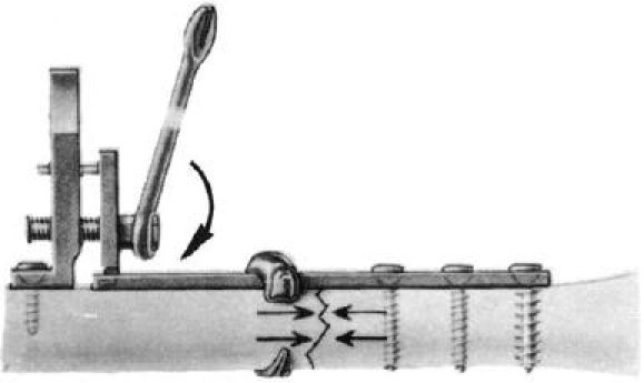
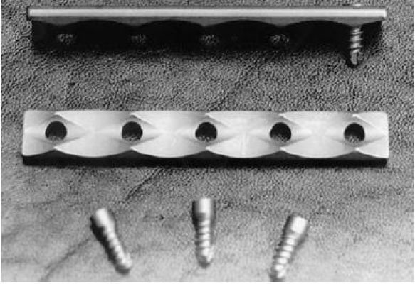
Figures 7C.1 to 7C.6: Uhthoff HK, Poitras P, Backman DS. J Orthop Sci 2006;11:118–126 (open access). Reproduced for non-commercial teaching.
7C.3.1 The scientific basis: primary bone healing
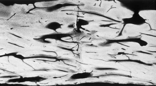
Danis had observed healing without callus on radiographs. The AO group wanted to know what happened in the bone itself. Schenk and Willenegger compressed osteotomies of the dog radius with plates and examined them under the microscope (Schenk and Willenegger 1963). They found that:
- Where the cortices were in contact, osteons grew directly across the osteotomy line. Osteoclasts at the tip of a cutting cone made a tunnel across the line, and osteoblasts behind them filled it with lamellar bone.
- Where a small stable gap remained, the gap first filled with lamellar bone laid down across it. This bone was later remodeled by osteons along the axis of the bone.
- There was no cartilage stage and no external callus.
The same finding was repeated in the rabbit (Rahn 1971). This gave compression plating a biological explanation: under absolute stability, bone heals by the same process that it uses for normal remodeling.
A second question had to be answered before compression could be recommended. Many surgeons believed that pressure on bone caused it to die and resorb. If this were true, compression would be lost within days. Perren fitted plates with strain gauges and measured the compression in living sheep for several months. The compression fell slowly over weeks to months, and there was no resorption of the compressed bone surfaces (Perren 1969b). Bone tolerates static compression. What causes resorption is movement, not pressure.
7C.3.2 The tension device and its drawbacks
By the mid-1960s the AO round-hole plate with the tension device worked well, and the principle was accepted. The remaining problem was practical. The steps were:
- Fix the plate to one fragment.
- Hook the tension device into the last hole at the other end of the plate.
- Fix the tension device to the bone with a separate screw, beyond the end of the plate.
- Tighten the device with a spanner to pull the plate and compress the fracture.
- Insert the remaining screws, then remove the device.
| Drawback of the tension device | Why it matters |
|---|---|
| Longer incision and more stripping | The device sits beyond the end of the plate. The wound must be several centimeters longer and more periosteum is lifted from the bone. |
| An extra screw hole in the bone | The hole is left empty when the device is removed. An empty hole is a stress riser. |
| Needs space | It cannot be used near a joint, on a short fragment or in a small bone. It is not practical on the mandible or in the hand. |
| Compression in one place only | All the compression comes from one end of the plate. A fracture at two levels cannot be compressed at each level. |
| Extra step | More operating time. The compression could be lost if the device slipped before the screws were in. |
This is the exact problem that the DCP solved. The principle of compression was already proven. What was missing was a way to compress the fracture using only the plate and its own screws.
7C.4 The design of the DCP
The tension device pulled the plate from outside. Perren's idea was to put the mechanism inside the screw hole. The German name of the plate describes it well: Spann-Gleitloch-Platte, the "tension gliding-hole plate".
7C.4.1 The spherical gliding principle
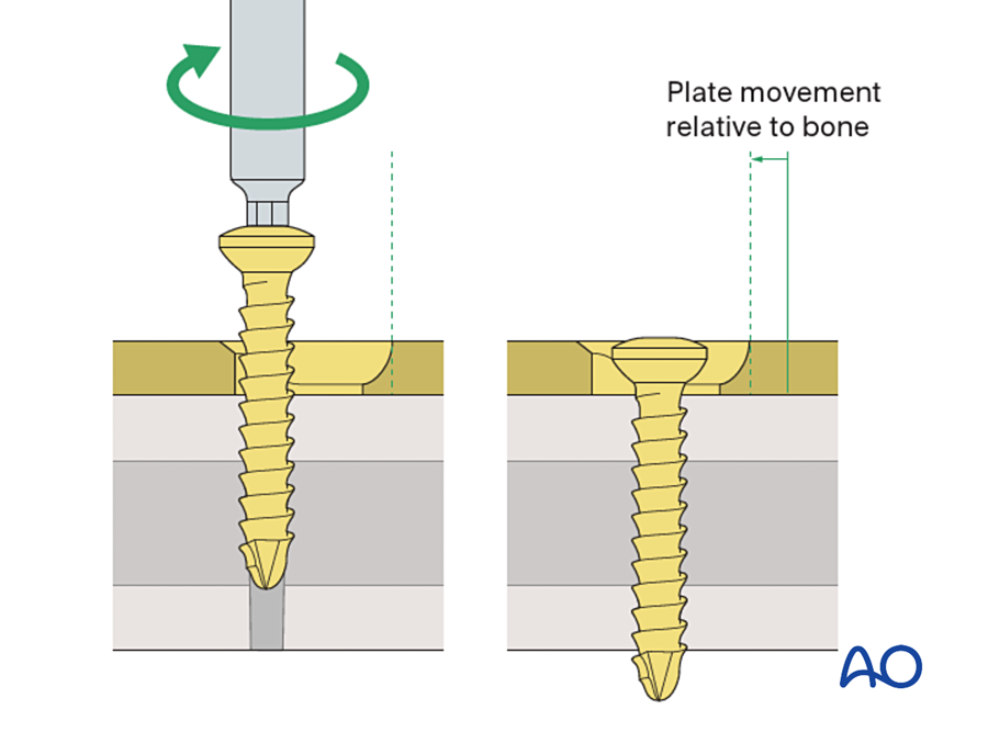
The design has two parts that fit each other:
- The screw head is rounded underneath, like half of a ball.
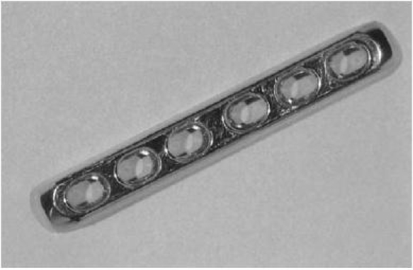
- The hole is oval. One end of the hole has a sloping wall. The other end is a horizontal seat. The shape is the same as a sloping cylinder that meets a horizontal cylinder.
The screw is placed at the high end of the slope, away from the fracture. As the screw is tightened it moves down into the bone, and the rounded head meets the slope. A ball on a slope cannot go straight down. It must also move sideways. The screw is fixed in the bone, so the screw and its bone fragment move sideways together, toward the fracture, while the plate stays still. When the head reaches the horizontal seat the sideways movement stops and the screw tightens fully.
7C.4.2 Load position and neutral position
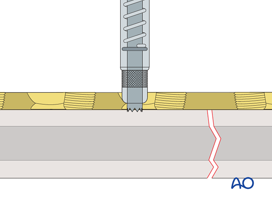
The surgeon decides what each screw does by choosing where to drill in the hole. Two drill guides are used. They look the same except for the position of the drill channel.
| Load (compression) guide | Neutral guide | |
|---|---|---|
| Color code | Gold (yellow) | Green |
| Position of the drill hole | 1.0 mm away from the center, on the side away from the fracture. The arrow on the guide points toward the fracture. | Almost central (0.1 mm off center) |
| Effect when the screw is tightened | The fragment moves 1.0 mm toward the fracture | The plate is pressed onto the bone. The very small offset adds a little compression and makes sure the screw never pushes the fragments apart. |
| Use | One screw in each main fragment, next to the fracture | All the other screws |
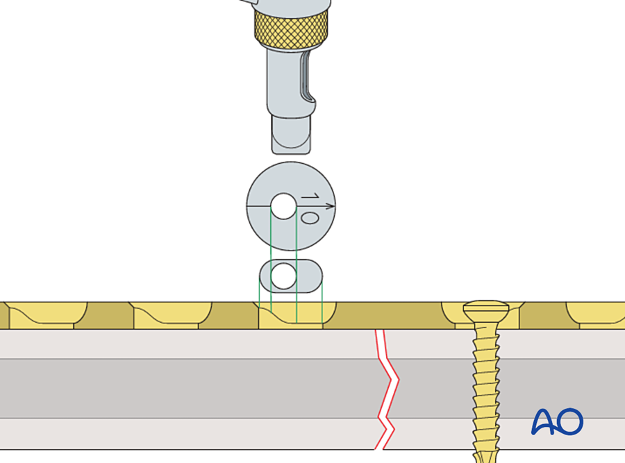
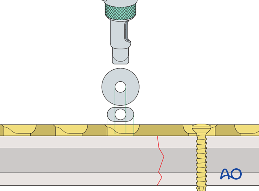
One load screw on each side of the fracture closes a gap of up to about 2 mm. If a gap remains, a third load screw can be added. The first load screw in that fragment is loosened, the new one is tightened, and the first is tightened again.
7C.4.3 Other features of the hole
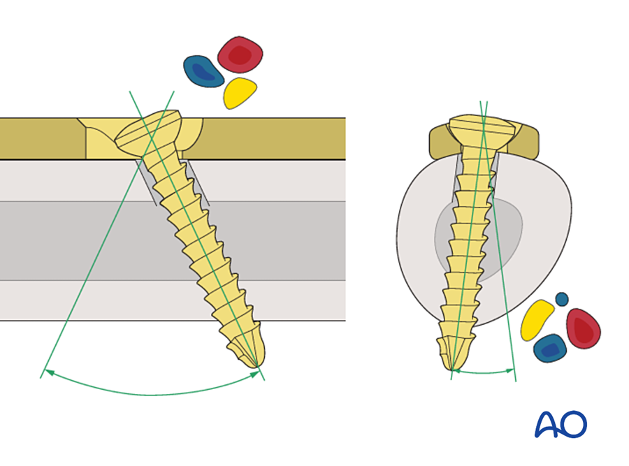
- The screw can be tilted. Because the head is rounded, the screw can be angled inside the hole: up to about 25° along the plate and 7° across it. A screw can therefore be placed through the plate as a lag screw across an oblique fracture, or directed away from a nerve or a tooth root.
- Every hole is the same. Any hole can be used for compression or in neutral. The surgeon does not have to decide before choosing the plate.
- The holes are directional. In the original DCP the slope of each hole faces the middle of the plate. The holes on the left half compress to the right and the holes on the right half compress to the left. The middle of the plate, which lies over the fracture, has no hole.
- Sizes. The first DCP was the 4.5 mm plate for the femur, tibia and humerus. The same hole was then made smaller: 3.5 mm for the forearm, 2.7 mm and 2.0 mm for the hand, and 2.4 mm and 2.0 mm plates for the mandible.
A note on the name. "Dynamic" refers to the movement of the screw head in the hole while the compression is being produced. Once the screw is tight, the compression is static. It does not increase with function. Some authors have criticized the name for this reason (Uhthoff 2006).
7C.5 Technique of compression plating
The hole produces compression. Whether that compression gives a stable fracture depends on how the plate is applied. The principles come first, then the steps.
7C.5.1 Principles
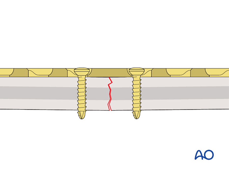
- The fracture must be simple. Compression needs two fragments that fit together: a transverse or short oblique fracture, or an osteotomy. A comminuted fracture collapses when it is compressed.
- Reduction must be anatomical, and it comes first. The gliding hole closes a gap of 1 to 2 mm. It is not a reduction tool.
- The plate goes on the tension side of the bone. A bone under bending load has one side in tension and one side in compression. A plate on the tension side stops the fracture from opening and turns the bending load into compression at the opposite cortex.
- The plate must be over-bent. This is explained next.
7C.5.2 Over-bending the plate
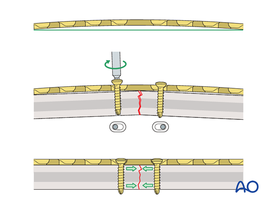
The plate lies on one surface of the bone. When it is put under tension, it compresses the cortex directly under it. The fracture then hinges on this near cortex and opens at the far cortex. The far cortex is left with a gap and no compression.
The solution is to bend the plate slightly more than the shape of the bone, so that its middle stands 1 to 2 mm off the bone over the fracture. As the screws pull the plate down onto the bone, the plate straightens. It acts as a spring and presses the far cortex closed.
7C.5.3 Steps for a transverse fracture
- Reduce the fracture and hold it with forceps.
- Contour the plate to the bone, then over-bend it at the level of the fracture.
- Insert the first screw next to the fracture in one fragment. Do not tighten it fully.
- Insert a load screw next to the fracture in the other fragment.
- Tighten the two screws in turn, a little at a time. The fracture closes and is compressed.
- Check the far cortex. If a gap remains, add a third load screw.
- Fill the remaining holes with screws in neutral position.
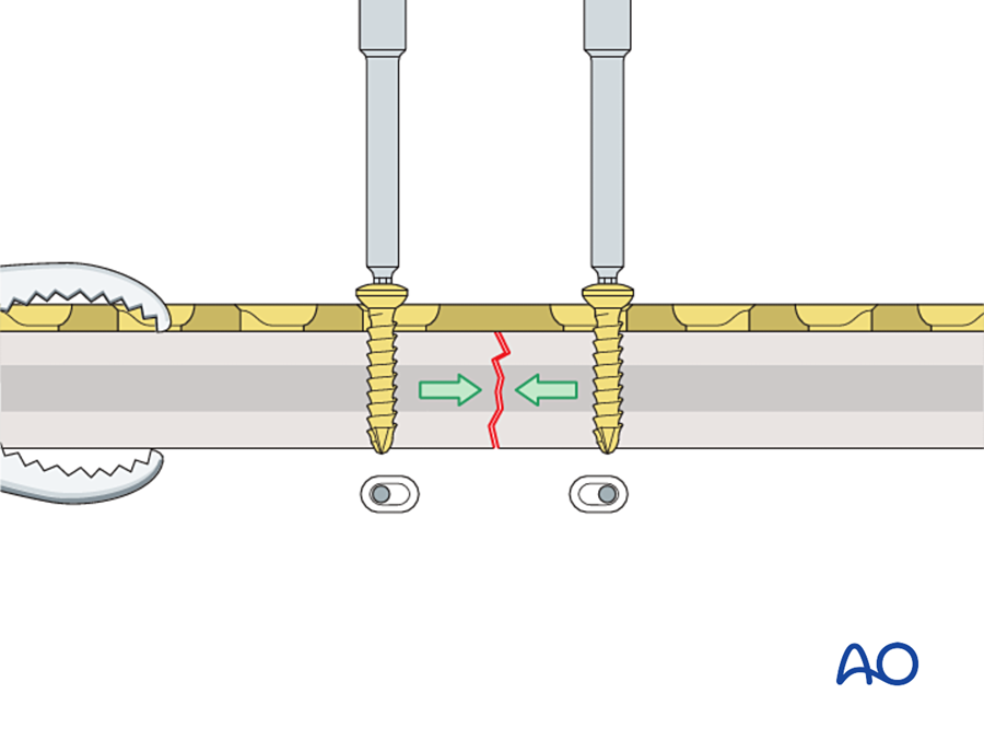
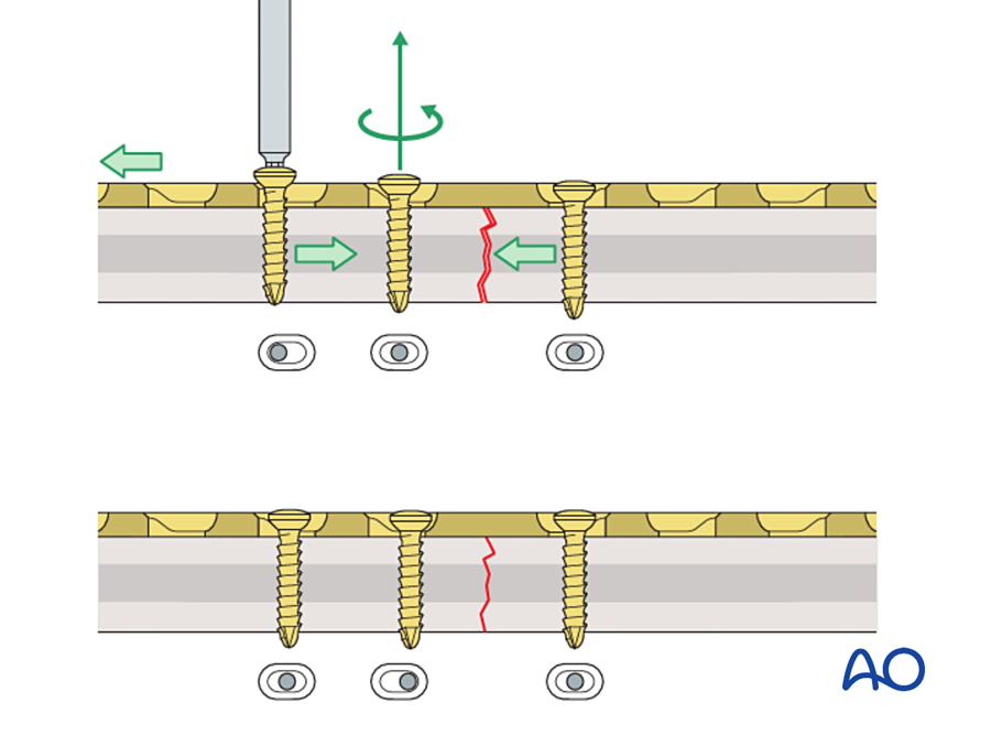
7C.5.4 Oblique fractures
If an oblique fracture is compressed along the bone, the two fragments slide past each other. To prevent this, the plate is first fixed to the fragment that forms an acute angle with the plate. This angle is called the axilla. The load screw is then placed in the other fragment. The pointed end of this fragment is pushed into the axilla and is trapped there, so it cannot slide. A lag screw placed through the plate across the fracture adds more compression.
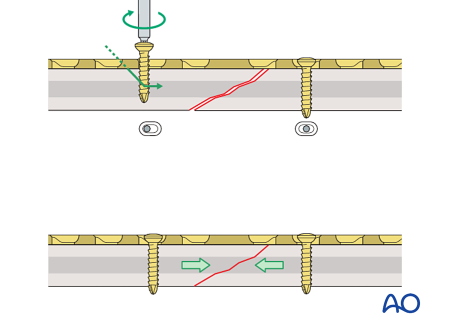
What this means in practice. A plate that can compress is not always compressing. On a postoperative radiograph, look at where each screw sits in its hole. A screw at the end of the hole nearest the fracture was used as a load screw. Screws in the center of the hole are neutral. A plate with every screw in neutral over a comminuted zone is working as a bridge, not as a compression plate.
7C.6 Why the DCP was an innovation
The DCP did not introduce a new principle. Compression came from Danis, and the oval hole had been drawn by Bagby. The innovation was that the DCP turned a difficult technique into a simple and repeatable one. The points below explain this.
| Feature | Before the DCP | With the DCP | Consequence |
|---|---|---|---|
| Source of compression | A separate tension device fixed to the bone | The slope inside the screw hole | No extra instrument, no extra hole in the bone |
| Exposure | Incision longer than the plate | Incision the length of the plate | Less periosteal stripping; the plate can be used near joints and on short fragments |
| Where compression is applied | From one end of the plate | At any hole, on either side of the fracture | Compression can be added in steps. A fracture at two levels can be compressed at both levels. |
| Function of each screw | Fixed by the design of the plate | Chosen by the surgeon at each hole: load, neutral, or lag screw through the plate | One plate can work as a compression plate, protection plate, buttress plate, tension band or bridge plate |
| Direction of the screw | Perpendicular to the plate | Can be tilted | A lag screw can cross an oblique fracture through the plate |
| Reproducibility | Depended on the skill of the surgeon with the tension device | Depends on a color-coded drill guide | The technique could be taught in courses and repeated in any hospital |
| Size | The tension device was too large for small bones | The hole can be made in any size | Compression plating reached the forearm, the hand and the mandible |
Three further points made the DCP different from earlier inventions.
1. It was tested before it was promoted. The Bagby plate had the same idea but no supporting research. The DCP was published together with measurements of the compression it produced, proof that bone does not resorb under static compression, and histology of the healing it gave (Perren 1969a, 1969b). This combination of engineering, animal experiment and clinical follow-up became the model for implant development.
2. It was part of a system. The plate came with matching screws, drills, taps and guides, with a written technique, with hands-on courses, and with a register of cases. Uhthoff, who was a critic of rigid plating, still wrote that careful surgical technique and an excellent teaching program were a large part of its success (Uhthoff 2006).
3. The clinical results were very good in the right fractures. The best example is the forearm. The radius and ulna must heal with exact length and rotation, and callus between them blocks pronation and supination. This is the ideal indication for absolute stability.
| Study | Patients | Implant | Result |
|---|---|---|---|
| Anderson et al. 1975 | 244 patients, 330 forearm shaft fractures, treated 1960 to 1970 | AO compression plates | Union: radius 97.9%, ulna 96.3%. No cast was used. |
| Chapman et al. 1989 | 87 patients, 129 forearm shaft fractures | AO dynamic compression plate | Union 98%. Excellent or satisfactory function 92%. Infection 2.3%. Two refractures after removal of 4.5 mm plates; none after removal of 3.5 mm plates. |
Before compression plating, forearm shaft fractures in adults had a high rate of nonunion and stiffness. A union rate near 98% with early movement was a real change in what patients could expect.
What compression does and does not do. Compression gives stability. It does not make bone form faster. Bagby thought that compression increased the rate of healing. Later work showed that primary healing under a compression plate is slow, because it depends on osteons crossing the fracture one at a time. The benefit to the patient is early function, not early union.
7C.7 Limitations of the DCP
The DCP was used very widely in the 1970s and 1980s. With large numbers of cases, its problems became clear. Most of them come from the same source: to work, the plate must be pressed hard against a bone that has been widely exposed.
| Problem | Explanation |
|---|---|
| Wide exposure | Anatomical reduction needs every fragment to be seen and handled. Periosteum and muscle are stripped, and the fragments lose blood supply. |
| Pressure on the periosteum | Stability depends on friction between the plate and the bone. The flat underside of the plate presses on the periosteal vessels along its whole length. |
| Bone loss under the plate | The cortex under the plate becomes porous in the first months. The cause is debated (see below). |
| Refracture after plate removal | The bone may break again through the old fracture or through a screw hole. This is the reason for the advice to leave plates for at least 15 to 18 months. |
| Healing is hard to see | There is no callus. The radiograph shows only that the fracture line slowly disappears. Callus, when it appears, is a sign that the fixation has moved. |
| Not suitable for comminution | There are no two surfaces to press together. Attempts to reduce every small fragment devascularize them. |
| Not suitable for weak bone | In osteoporotic or very thin bone the screws strip before enough friction is produced. |
| Uneven stiffness | The plate is weaker at each hole than between holes. When it is bent, it kinks at the holes. |
| Compression in one direction per hole | Each hole slopes only toward the middle of the plate. |
7C.7.1 Bone loss under the plate: two explanations
Both explanations are still quoted, and the question is not fully settled.
| Stress shielding | Vascular damage | |
|---|---|---|
| Proposed by | Uhthoff and Dubuc 1971, and others | Perren and colleagues 1988 |
| Idea | The stiff plate carries the load. The bone under it is unloaded and is resorbed, as Wolff's law predicts. | The plate compresses the periosteal vessels. The cortex under it dies. The porosity is the normal remodeling that removes and replaces dead bone. |
| Evidence given | In dogs, the porosity was greatest in the inner (endosteal) half of the cortex, and the cortex became permanently thinner | In sheep, the area of porosity matched the area of lost blood supply, not the area of unloading. Flexible plastic plates caused as much porosity as steel. The porosity was temporary. |
| Design answer | A less stiff plate | A plate that touches less of the bone |
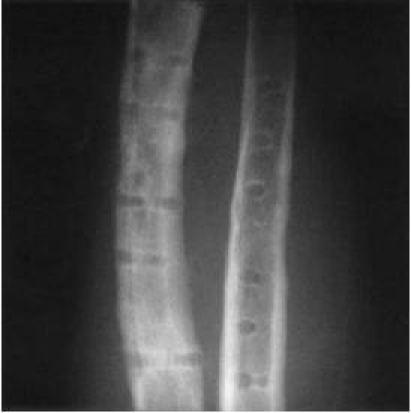
The AO group followed the vascular explanation. This led directly to the next generation of plates.
7C.8 The plates that followed the DCP
Each later plate kept part of the DCP and changed the part that caused harm. The direction of change was always the same: less contact with the bone, less exposure, and less dependence on friction.
Flowchart: From the DCP to the locking compression plate
- Round-hole plate and tension device1965
- DCP1969
- LC-DCP1990
- PC-Fix1990s
- LCP2001
| Plate | What changed | What it gained | What it kept or lost |
|---|---|---|---|
| Limited-contact DCP (LC-DCP) Perren 1990 | The underside is cut away between the holes, so only part of the plate touches the bone. The cross-section is a trapezoid. The holes are symmetrical and evenly spaced. Made in titanium. | Less pressure on the periosteal vessels. Even stiffness, so the plate bends smoothly. Compression in either direction from every hole. The screw can be tilted up to 40° along the plate. | Still a compression plate. Still needs friction and an exact fit. |
| Point contact fixator (PC-Fix) Tepic and Perren 1995 | The screw head locks into the plate. The plate touches the bone only at small points. Screws hold one cortex only. | The plate is not pressed onto the bone at all. It works like an external fixator placed under the skin. | No compression. Interfragmentary compression was given up on purpose. |
| Locking compression plate (LCP) Frigg 2001 | The combination hole: one half is a DCP gliding hole, the other half is threaded for a locking screw. | The surgeon can choose compression, locking, or both in the same plate. Compatible with the existing screws and instruments. | A locking screw cannot compress. If compression is wanted, the conventional screw must be placed first, and the locking screws after it. |
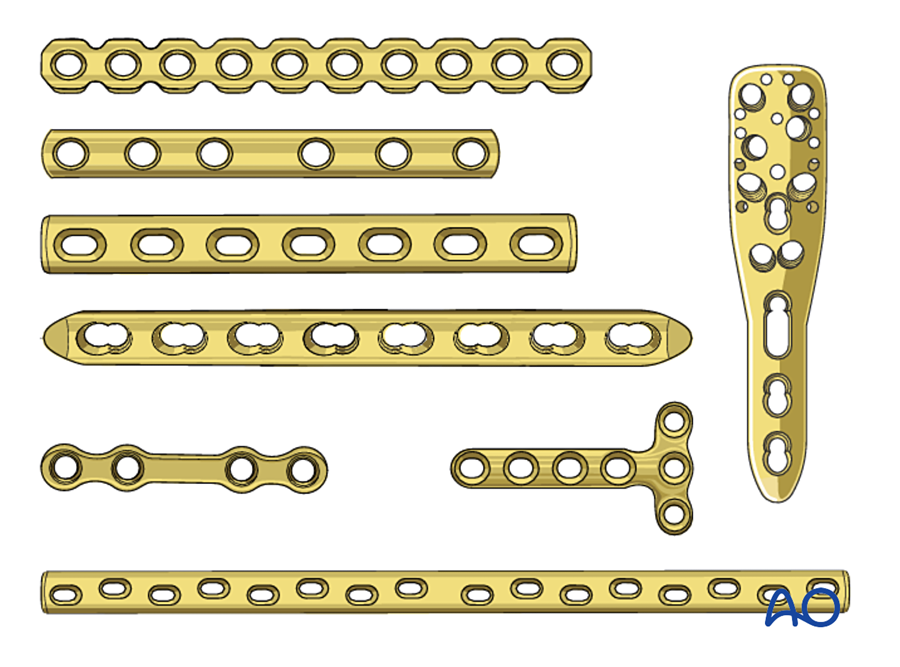
Did limited contact help? The evidence is weaker than the theory. A cadaver study found no clear difference in contact area between the DCP and the LC-DCP on the femur (Field 1997). A randomized study in dogs found no difference in cortical blood flow or in the strength of the healed bone (Jain 1999). Clinical union rates with the DCP and the LC-DCP are similar (Uhthoff 2006). The larger benefit probably came from the change in surgical technique that went with the new plates: less stripping, indirect reduction, and bridging of comminuted zones instead of piece-by-piece reduction.
The change in thinking. In the DCP period, callus after plating was read as a sign of failure. With biological fixation, callus is expected and welcome. The modern position is that both are correct, for different fractures:
| Compression (the DCP principle) | Bridging (the locking plate principle) | |
|---|---|---|
| Fracture | Simple, two fragments; osteotomy; joint surface | Comminuted; bone defect; weak bone |
| Reduction | Anatomical, open | Length, axis and rotation only |
| Stability | Absolute | Relative |
| Healing | Primary, no callus | Secondary, with callus |
The common error is to mix the two: a simple fracture bridged with a gap by a stiff locking plate. The gap is narrow, the strain is high, and the fracture does not unite. A simple fracture should be compressed.
7C.9 Compression plating in the mandible
The history of the DCP in the facial skeleton is short and important. It explains why we fix the mandible the way we do today.
7C.9.1 Luhr and Spiessl
Until the 1960s mandibular fractures were treated with wire osteosynthesis and four to six weeks of intermaxillary fixation. The limb instruments of the AO, including the tension device, were too large for the jaw. In 1967 Hans Luhr in Germany performed the first compression plating of the mandible, using a Vitallium plate with eccentric holes that he developed for this purpose (Luhr 1968). Soon afterward Bernd Spiessl in Basel adapted the AO dynamic compression plate to the mandible (Spiessl 1972). For the first time a patient with a fractured mandible could open the mouth and eat a soft diet immediately after surgery.
7C.9.2 The special problem of the mandible
The plate should be placed on the tension side of a bone. In the mandibular body and angle, the tension side is the upper (alveolar) border and the compression side is the lower border. But a large bicortical compression plate cannot be placed on the alveolar border. The tooth roots and the inferior alveolar nerve are in the way. It has to go on the lower border, which is the wrong side.
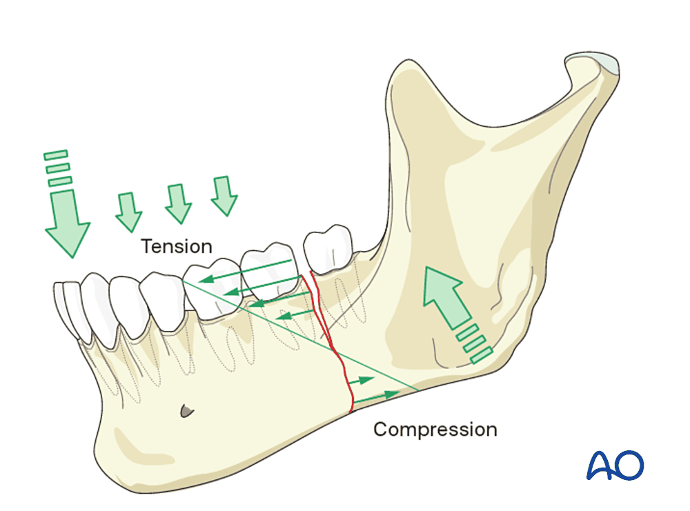
A compression plate on the lower border closes the lower border and opens the alveolar border. The result is a gap between the teeth and a changed occlusion. Two solutions were developed:
- A tension band. An arch bar on the teeth, or a small plate at the upper border, holds the tension side closed. The compression plate is then applied at the lower border.
- The eccentric dynamic compression plate (EDCP). The two inner holes compress along the plate as usual. The two outer holes are set obliquely, so that their screws rotate the fragments and press the alveolar border together (Schmoker and Spiessl 1973). It was used where a tension band could not be applied, for example at the angle when the proximal fragment had no teeth.
7C.9.3 Results, and why miniplates replaced compression plates
Compression plating of the mandible worked, but it was demanding.
| Study | Method | Result |
|---|---|---|
| Iizuka and Lindqvist 1992 | 270 mandibular fractures in 214 patients, AO rigid fixation | Good bone healing in 93.9%. Infection in 6.1%, in every case related to inadequate stability. Malocclusion in 18.2% of dentate patients, caused by incorrect plate bending and insufficient reduction. |
| Ellis and Sinn 1993 | 65 angle fractures, two 2.4 mm dynamic compression plates, transoral | Infection needing further surgery in 32%. The authors called this rate unacceptable. |
| Ellis 1999 | Eight methods for angle fractures compared in the same hospital population | Fewest complications with a single non-compression miniplate, or with a reconstruction plate |
| Luhr et al. 1996 | 84 fractures of the atrophic edentulous mandible, compression plating | Uncomplicated union in 96.5% |
The malocclusion rate shows the weakness of a rigid compression plate in the face. The plate is stiff and the screws pull the bone to the plate. If the plate is bent with an error of a fraction of a millimeter, the fragments move to fit the plate and the teeth no longer meet. In a long bone this error is not noticed. In the mandible the patient feels it at once.
At the same time Michelet (1973) and Champy (1978) showed that the mandible does not need compression at all. A small monocortical plate on the tension side, along the ideal lines of osteosynthesis, turns the forces of chewing into compression at the lower border. The plate is placed through the mouth, without a skin scar, without risk to the nerve, and with little periosteal stripping. The bone shares the load.
| Compression plate (Luhr, Spiessl) | Miniplate (Michelet, Champy) | |
|---|---|---|
| Position | Lower border | Upper border, along the ideal lines |
| Screws | Bicortical | Monocortical |
| Approach | Usually through the skin | Through the mouth |
| Stability | Absolute | Functionally stable; load-sharing |
| Source of compression | The plate | The muscles of mastication, through the tension band effect |
| Tolerance of bending error | Very low | Higher, because the plate is malleable |
Today compression plates are rarely used in facial fractures. Simple fractures are treated with miniplates. Comminuted fractures, defects and atrophic mandibles are treated with a load-bearing locking reconstruction plate. Compression is still used in the face in one form: the lag screw, for oblique fractures of the symphysis and body and for fixing onlay bone grafts.
What this means in practice. The mandible repeated the history of the long bones in a shorter time: first rigid compression, then a move to smaller implants that respect the blood supply and let the bone share the load. The lesson is the same in both. Compression is one tool. It should be chosen when the fracture is simple and the bone is good, and not as a routine.
7C.10 Where the principle is used in plastic and reconstructive surgery today
We seldom apply a large DCP, but we use its hole and its principle often.
| Situation | How the principle is used |
|---|---|
| Hand: transverse metacarpal and phalangeal fractures | A transverse fracture has no oblique plane for a lag screw. A 1.5 or 2.0 mm plate with gliding holes, placed on the dorsal (tension) side, compresses it with one eccentric screw. Stable fixation allows early tendon gliding, which is the main aim in the hand. |
| Hand: osteotomy and arthrodesis | Corrective osteotomy for malunion and fusion of small joints both need two flat cancellous or cortical surfaces pressed together. This is the same situation as a compressed osteotomy in the laboratory studies of primary healing. |
| Replantation and revascularization at forearm or hand level | The bone is shortened to allow vessel and nerve repair without tension. This creates two clean transverse surfaces, which are suited to a compression plate. Fast, stable bone fixation is done first because all the later repairs depend on it. |
| Forearm fractures in a mangled limb | The radius and ulna are plated with 3.5 mm compression plates when the fracture is simple, and bridged when it is comminuted. The flap is planned around the plate. |
| Osteocutaneous radial forearm flap: the donor radius | Removing part of the radius weakens it, and fracture of the donor radius was the main objection to this flap. A plate is now applied to the remaining radius at the time of harvest. In one series, 52 of 54 donor radii were plated and none had a clinically significant fracture (Werle 2000). In another, none of 34 plated radii fractured (Villaret and Futran 2003). Here the plate does not compress anything. It protects the bone from bending and torsion, like a protection plate. |
| Free fibula and other bone flaps | The osteotomies between segments are closed by hand and held with miniplates or a reconstruction plate. Compression holes are not used. The segments are small, their periosteal blood supply must not be disturbed, and the purpose of the plate is to hold the planned shape. |
| Mandibular and midface osteotomies | Stable contact between the bone surfaces is wanted, but compression would change the occlusion or injure the nerve. Position screws and passive miniplates are used instead. |
| Onlay and inlay bone grafts | A lag screw presses the graft against the recipient bed. Compression and absolute stability allow the graft to revascularize and unite without resorption caused by movement. |
| Reading a radiograph | After compression fixation, no callus is normal. New callus around a compression plate means that the fixation is moving. |
In every row the same three conditions decide whether compression is the right choice: two surfaces that fit, bone strong enough to hold screws, and a blood supply that survives the exposure.
7C.11 Summary
- Before the 1950s, fractures were immobilized for weeks and patients were left with stiff, weak limbs. Early plates failed from corrosion and then from lack of strength.
- Danis (1949) showed that a compressed fracture heals without callus. Bagby (1956) drew a self-compressing oval hole. Müller and the AO (1958 to 1965) made compression plating a system, using a separate tension device.
- The DCP (Perren 1969) put the compression mechanism inside the screw hole. A screw placed 1.0 mm off center slides down a slope and moves its fragment toward the fracture.
- It was an innovation because it made compression simple, repeatable and possible in any size of bone, and because it was supported by experimental proof and a teaching system.
- Its limits were wide exposure, pressure on the periosteum, bone loss under the plate and poor results in comminuted fractures. These led to the LC-DCP, the PC-Fix and the locking compression plate.
- In the mandible, compression plates (Luhr 1968, Spiessl 1972) gave the first stable fixation without intermaxillary fixation, but they were replaced by miniplates and reconstruction plates.
- In plastic surgery the principle remains in small plates for the hand, in lag screws, and in the combination hole of modern locking plates.
References
- Perren SM, Russenberger M, Steinemann S, Müller ME, Allgöwer M. A dynamic compression plate. Acta Orthop Scand Suppl 1969;125:31–41. (Perren 1969a)
- Perren SM, Huggler A, Russenberger M, Allgöwer M, Mathys R, Schenk R, Willenegger H, Müller ME. The reaction of cortical bone to compression. Acta Orthop Scand Suppl 1969;125:19–29. (Perren 1969b)
- Allgöwer M, Perren S, Matter P. A new plate for internal fixation: the dynamic compression plate (DCP). Injury 1970;2:40–47.
- Uhthoff HK, Poitras P, Backman DS. Internal plate fixation of fractures: short history and recent developments. J Orthop Sci 2006;11:118–126.
- Perren SM. Evolution of the internal fixation of long bone fractures. J Bone Joint Surg Br 2002;84:1093–1110.
- Lane WA. Some remarks on the treatment of fractures. Br Med J 1895;1:861–863.
- Sherman WO. Vanadium steel bone plates and screws. Surg Gynecol Obstet 1912;14:629–634.
- Venable CS, Stuck WG, Beach A. The effects on bone of the presence of metals; based upon electrolysis. Ann Surg 1937;105:917–938.
- Eggers GWN. Internal contact splint. J Bone Joint Surg Am 1948;30:40–52.
- Danis R. Théorie et pratique de l'ostéosynthèse. Paris: Masson; 1949.
- Bagby GW, Janes JM. The effect of compression on the rate of fracture healing using a special plate. Am J Surg 1958;95:761–771.
- Schenk R, Willenegger H. Zum histologischen Bild der sogenannten Primärheilung der Knochenkompakta nach experimentellen Osteotomien am Hund. Experientia 1963;19:593–595.
- Rahn BA, Gallinaro P, Baltensperger A, Perren SM. Primary bone healing. An experimental study in the rabbit. J Bone Joint Surg Am 1971;53:783–786.
- Anderson LD, Sisk D, Tooms RE, Park WI. Compression-plate fixation in acute diaphyseal fractures of the radius and ulna. J Bone Joint Surg Am 1975;57:287–297.
- Chapman MW, Gordon JE, Zissimos AG. Compression-plate fixation of acute fractures of the diaphyses of the radius and ulna. J Bone Joint Surg Am 1989;71:159–169.
- Uhthoff HK, Dubuc FL. Bone structure changes in the dog under rigid internal fixation. Clin Orthop Relat Res 1971;81:165–170.
- Perren SM, Cordey J, Rahn BA, Gautier E, Schneider E. Early temporary porosis of bone induced by internal fixation implants. A reaction to necrosis, not to stress protection? Clin Orthop Relat Res 1988;232:139–151.
- Klaue K, Fengels I, Perren SM. Long-term effects of plate osteosynthesis: comparison of four different plates. Injury 2000;31 Suppl 2:B51–B62.
- Perren SM, Klaue K, Pohler O, Predieri M, Steinemann S, Gautier E. The limited contact dynamic compression plate (LC-DCP). Arch Orthop Trauma Surg 1990;109:304–310.
- Field JR, Hearn TC, Caldwell CB. Bone plate fixation: an evaluation of interface contact area and force of the dynamic compression plate (DCP) and the limited contact-dynamic compression plate (LC-DCP) applied to cadaveric bone. J Orthop Trauma 1997;11:368–373.
- Jain R, Podworny N, Hupel TM, Weinberg J, Schemitsch EH. Influence of plate design on cortical bone perfusion and fracture healing in canine segmental tibial fractures. J Orthop Trauma 1999;13:178–186.
- Tepic S, Perren SM. The biomechanics of the PC-Fix internal fixator. Injury 1995;26 Suppl 2:B5–B10.
- Frigg R. Locking compression plate (LCP). An osteosynthesis plate based on the dynamic compression plate and the point contact fixator (PC-Fix). Injury 2001;32 Suppl 2:63–66.
- Frigg R. Development of the locking compression plate. Injury 2003;34 Suppl 2:B6–B10.
- Luhr HG. Zur stabilen Osteosynthese bei Unterkieferfrakturen. Dtsch Zahnarztl Z 1968;23:754.
- Luhr HG. Entwicklung der modernen Osteosynthese. Mund Kiefer Gesichtschir 2000;4 Suppl 1:S84–S90.
- Spiessl B. Rigid internal fixation of fractures of the lower jaw. Reconstr Surg Traumatol 1972;13:124–140.
- Schmoker R, Spiessl B. Exzentrisch-dynamische Kompressionsplatte. SSO Schweiz Monatsschr Zahnheilkd 1973;83:1496–1509.
- Schmoker R, Spiessl B, Tschopp HM, Prein J, Jaques WA. Die funktionsstabile Osteosynthese am Unterkiefer mittels einer exzentrisch-dynamischen Kompressionsplatte. SSO Schweiz Monatsschr Zahnheilkd 1976;86:167–185.
- Michelet FX, Deymes J, Dessus B. Osteosynthesis with miniaturized screwed plates in maxillo-facial surgery. J Maxillofac Surg 1973;1:79–84.
- Champy M, Loddé JP, Schmitt R, Jaeger JH, Muster D. Mandibular osteosynthesis by miniature screwed plates via a buccal approach. J Maxillofac Surg 1978;6:14–21.
- Iizuka T, Lindqvist C. Rigid internal fixation of mandibular fractures. An analysis of 270 fractures treated using the AO/ASIF method. Int J Oral Maxillofac Surg 1992;21:65–69.
- Ellis E, Sinn DP. Treatment of mandibular angle fractures using two 2.4-mm dynamic compression plates. J Oral Maxillofac Surg 1993;51:969–973.
- Ellis E. Treatment methods for fractures of the mandibular angle. Int J Oral Maxillofac Surg 1999;28:243–252.
- Luhr HG, Reidick T, Merten HA. Results of treatment of fractures of the atrophic edentulous mandible by compression plating: a retrospective evaluation of 84 consecutive cases. J Oral Maxillofac Surg 1996;54:250–254.
- Werle AH, Tsue TT, Toby EB, Girod DA. Osteocutaneous radial forearm free flap: its use without significant donor site morbidity. Otolaryngol Head Neck Surg 2000;123:711–717.
- Villaret DB, Futran NA. The indications and outcomes in the use of osteocutaneous radial forearm free flap. Head Neck 2003;25:475–481.
- AO Surgery Reference. Plating: basic principles; Screw insertion in compression mode; Screw insertion in neutral mode; Biomechanics of the mandible. AO Foundation. surgeryreference.aofoundation.org